S8VS
32
Safety Precautions
!CAUTION
Minor electric shock, fire, or Product failure may
occasionally occur. Do not disassemble, modify, or
repair the Product or touch the interior of the
Product.
Minor burns may occasionally occur. Do not touch
the Product while power is being supplied or
immediately after power is turned OFF.
Fire may occasionally occur. Tighten terminal screws
to the specified torque (15- and 30-W models: 0.8 to
1.0 N·m/60-, 90-,120-, 180-, 240-, and 480-W models:
1.08 N·m).
Minor injury due to electric shock may occasionally
occur. Do not touch the terminals while power is
being supplied. Always close the terminal cover after
wiring.
Minor electric shock, fire, or Product failure may
occasionally occur. Do not allow any pieces of metal
or conductors or any clippings or cuttings resulting
from installation work to enter the Product.
Mounting
• Take adequate measures to ensure proper heat dissipation to
increase the long-term reliability of the Product. Be sure to allow
convection in the atmosphere around devices when mounting. Do
not use in locations where the ambient temperature exceeds the
range of the derating curve.
• When cutting out holes for mounting, make sure that cuttings do
not enter the interior of the Products.
15-W and 30-W Models
• Improper mounting will interfere with heat dissipation and may
occasionally result in deterioration or damage of internal parts. Use
the Product within the derating curve for the mounting direction that
is used.
• Use a mounting bracket when the Product is mounted facing
horizontally.
• Heat dissipation will be adversely affected. When the Product is
mounted facing horizontally, always place the side with the label
facing upward.
• Operate the Power Supply within a range that is 5°C less than the
values in the derating curve in Engineering Data on page 18 if the
Power Supply is used with an installation spacing of 10 mm min.
(20 mm max.) on the left and right.
60-W, 90-W, 120-W, 180-W, 240-W, and 480-W Models
• Improper mounting will interfere with heat dissipation and may
occasionally result in deterioration or damage of internal parts. Use
the standard mounting method only.
• The internal parts may occasionally deteriorate and be broken due
to adverse heat radiation. Do not loosen the screw on the side face
of the main body.
Wiring
• Connect the ground completely. A protective earthing terminal
stipulated in safety standards is used. Electric shock or malfunction
may occur if the ground is not connected completely.
• Minor fire may possibly occur. Ensure that input and output
terminals are wired correctly.
• Do not apply more than 100-N force to the terminal block when
tightening it.
• Be sure to remove the sheet covering the Product for machining
before power-ON so that it does not interfere with heat dissipation.
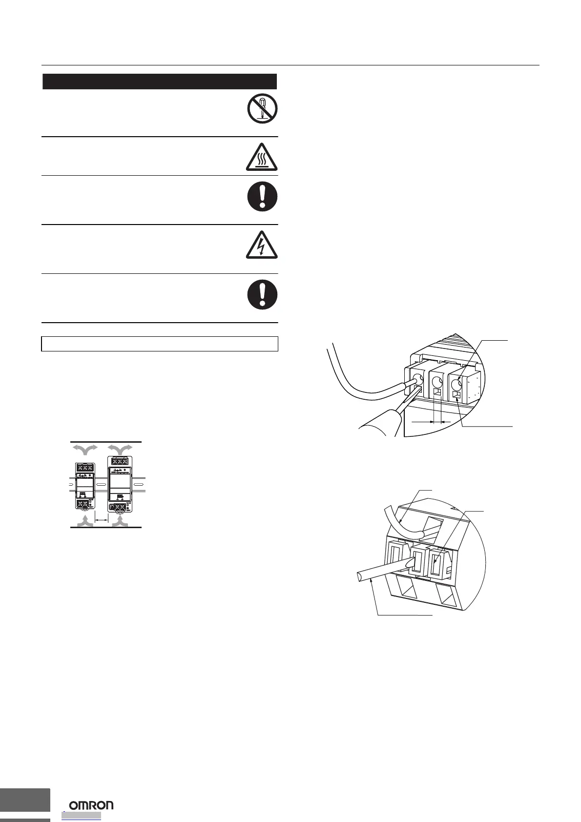
• When wiring a screwless terminal block, do not insert more than
one wire into a single terminal.
• When using a screwless terminal block, connect or disconnect the
I/O wire to each terminal while inserting an appropriate tool, such
as a flat-blade screwdriver, into the tool insertion hole. Make sure
that the wire is securely connected to the terminal after wiring. Do
not insert wires into the tool insertion holes.
If a wire is not inserted far enough or if it is loose, electric shock,
fire, or equipment failure may occur. Strip the wires according to
specifications. Insert an appropriate tool, such as a flat-blade
screwdriver, into the tool insertion hole, insert the wire until the
stripped portion is no longer visible, and then remove the tool.
Make sure that the wires are securely connected to the terminal
block after wiring. Never insert wires into the tool insertion holes.
• The method of use Alarm output terminal
The method of use Alarm output terminal is push the button then
insert or pull out the wire.
Please make sure that the wire is already fixed on the terminal.
Precautions for Safe Use
*1
*1
*2
*1. Convection of air
*2. 20 mm min.
Tool insertion hole
3.7 mm
Wire hole
flat-bladescrewdriver
button
wire
Downloaded from Arrow.com.Downloaded from Arrow.com.Downloaded from Arrow.com.Downloaded from Arrow.com.Downloaded from Arrow.com.Downloaded from Arrow.com.Downloaded from Arrow.com.Downloaded from Arrow.com.Downloaded from Arrow.com.Downloaded from Arrow.com.Downloaded from Arrow.com.Downloaded from Arrow.com.Downloaded from Arrow.com.Downloaded from Arrow.com.Downloaded from Arrow.com.Downloaded from Arrow.com.Downloaded from Arrow.com.Downloaded from Arrow.com.Downloaded from Arrow.com.Downloaded from Arrow.com.Downloaded from Arrow.com.Downloaded from Arrow.com.Downloaded from Arrow.com.Downloaded from Arrow.com.Downloaded from Arrow.com.Downloaded from Arrow.com.Downloaded from Arrow.com.Downloaded from Arrow.com.Downloaded from Arrow.com.Downloaded from Arrow.com.Downloaded from Arrow.com.Downloaded from Arrow.com.

 Loading...