No. 20S071-01
STC-HD213DV / STC-HD213DV-CS / STC-HD213SDI / STC-HD213SDI-CS /
STC-HD213DVN / STC-HD213DVN-CS / STC-HD213SDIN / STC-HD213SDIN-CS
Product Specifications and User
20/94
6.2 Camera Setting through External Switch (Remote Controller)
Remote controller (Model:RC-HD133) is option, remote controller is not included camera
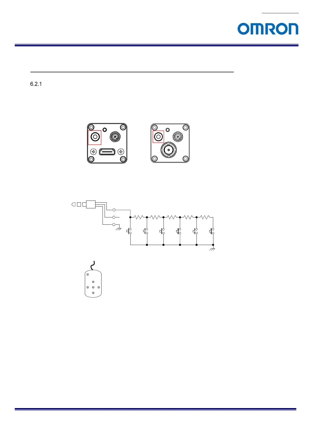
Camera Setting through Switch that has 3.5φStereo Pin Jack
A. Please assign each function through control software in advance
B. Connector
The location of 3.5φStereo Pin Jack for each model
C. Switch Circuit Diagram,
D. Example
E. Switch Function
The button from SW-A to SW-F can be assigned as follow functions.
SW-A: Show OSD Menu
SW-B: Up Cursor (Menu and Select Setting)
SW-C: Left Cursor (Select Setting)
SW-D: Execute
SW-E: Right Cursor (Select Setting)
SW-F: Down Cursor (Menu and Select Setting)
Tip
GND
SW-A SW-B SW-C SW-D SW-E SW-F
1 2
1 2
1 2
1 2
1 2
1 2
R1
1.8K
R2
3.3K
R3
4.7K
R4
10K
R5
27K
SW-A
SW-B
SW-D
SW-C SW-E
SW-F

 Loading...


