3
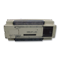
Beneath the cover are the DIP switch and the socket where an EPROM chip
may be installed. For details, see 2-8-1 Setting the CPU DIP Switch and
2-8-2 EPROM Installation. Only DIP switch pins 1 and 2 are on when the
CPU is delivered.
ROM socket
8 Turn ON to use hardware reset (0001).
7 Turn OFF if FUN 61 is not used.
6 Turn ON for English display.
5 Turn ON to inhibit ALARM indicator.
4, 3 ROM: ON (RAM: OFF)
2, 1 RAM: ON (ROM: OFF)
CAUTION: In case of battery failure, data stored in
the RAM, the DM area, the HR area, etc., will not be preserved.
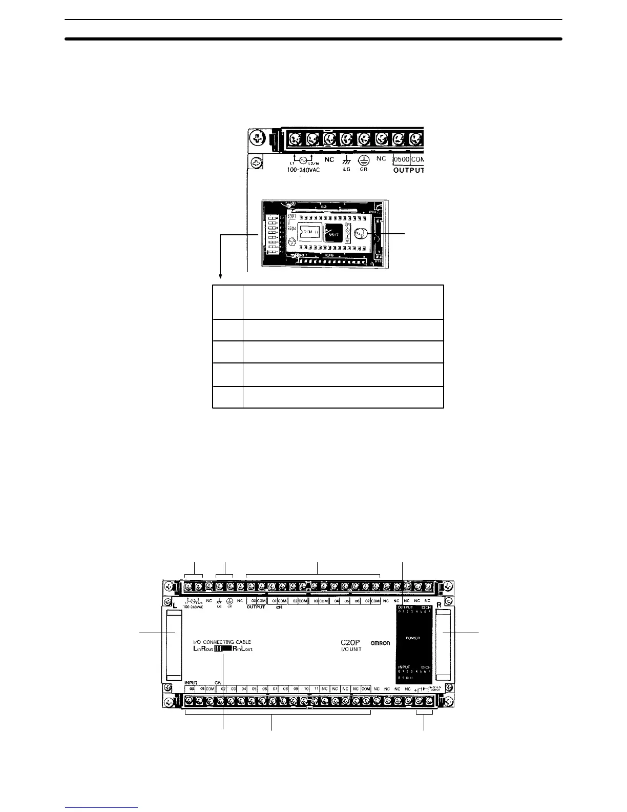
1-1-2 Expansion I/O Units
In the diagram below, the C20P is shown as a representative model. Refer to
Appendix A Standard Models for your model’s exact specifications.
Power supply Ground Outputs Indicators
CPU,
Expansion
I/O Unit,
Analog Timer
Unit, Analog
I/O Unit, or
I/O Link Unit
connector
24-VDC outputInputsCPU left/right
selector
CPU,
Expansion
I/O Unit, or
I/O Link Unit
connector
ROM Socket and DIP
Switch
Nomenclature Section 1-1
 Loading...