6
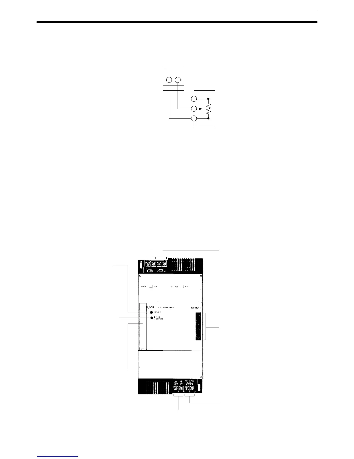
External Variable Resistor The contactor employs solderless terminals and must be wired as shown be-
low, using AWG 22 to 28 lead wires.
Analog Timer Unit
connector
External variable
resistor (20 kW)
1-1-4 I/O Link Units
The I/O Link Unit must be used as a Remote I/O Slave, and must be used
with a Remote I/O Master. Refer to the Remote I/O Unit Operation Guide for
details.
Operation output terminal
Indicates that the power is ON
and that the CPU is in RUN or
MONITOR mode with no errors.
Repeater Output Terminal
Sends repeater signals to a Link
Adapter. The repeater output is ON
when power is ON in the CPU and
I/O Link Unit. (See the Link Adapter
Manual for details.)
Optical fiber connectors
Transmitting error indicator
Blinks during normal transmission.
Lights continuously to indicate a
transmission or connection error.
AC power supply
Ground
CPU or Expansion
I/O Unit connector
Power indicator
Nomenclature Section 1-1
 Loading...