5-4
Controller A1 Removal / Replacement
To remove the controller, remove the two-piece en-
closure, which is secured by four screws to the en-
gine/generator base. Make sure to remove the
screw in back of the rear section of the enclosure.
Then remove the two screws that secure the con-
troller to the rear section of the enclosure and slide it
out. Use a small flat-bladed screwdriver to lever out
the catch on connector P1/J1 (Figure 5-3), and pull
the connector apart.
OTHER CONTROL COMPONENTS
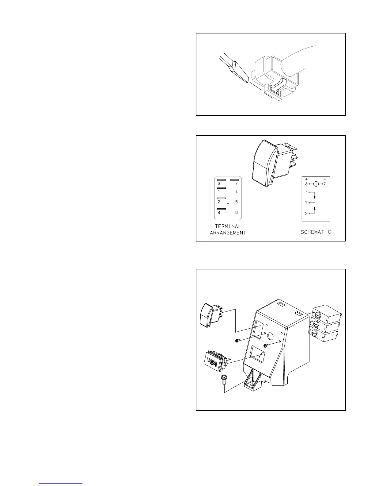
Control Switch S1
The control switch (Figure 5-4) is located as shown
(Figure 5-5). Unsnap connector P9 from the back of
the switch for access to its terminals. Replace the
switch if it does not: close across terminals 2 and 3
when the switch is held in the Start position, close
across terminals 1 and 2 when held in the Stop posi-
tion, or the status indicator light does not light when
12 VDC is connected across terminals 7 (–) and
8 (+).
Line Circuit Breakers CB1, CB2, CB3
The line circuit breakers are located as shown (Fig-
ure 5-5). Disconnect all wiring and check electrical
resistance across the terminals of each circuit
breaker. Replace a circuit breaker that does not re-
set or that does not close or open as the handle is
turned ON and OFF.
Hour Meter
When the genset is so equipped, the hour meter is
located as shown (Figure 5-5).
FIGURE 5-3. DISCONNECTING P1 / J1
FIGURE 5-4. CONTROL SWITCH S1
FIGURE 5-5. CONTROL SWITCH, LINE CIRCUIT
BREAKERS, HOUR METER
 Loading...


