6-1
6. Engine and Accessories
MAJOR ENGINE SERVICE
WARNING
Accidental or remote starting can
cause severe personal injury or death. Before
removing a panel or access door, disconnect
the negative (–) cable at the battery to prevent
the engine from starting.
Refer to engine Workshop Manual 981-0533 for
major engine service and for servicing fuel injectors,
setting fuel injection timing, replacing glow plugs,
cleaning the crankcase breather assembly and re-
placing the coolant pump.
Note: To preserve the existing high-idle speed ad-
justment, do not disturb the lock wires on the adjust-
ing screws on the governor actuator base
(Page 6-7) when removing it from the engine for en-
gine service.
Cooling System: Refer to ENGINE COOLING
SYSTEM (Page 4-6) for replacing thermostat, raw
water impeller, heat exchanger and V-belt.
Fuel Injection Timing Marks: Note the fuel injec-
tion timing marks (Figure 6-1), which line up at
19° BTDC. They are visible when the back or side
panel is removed (Page 5-1).
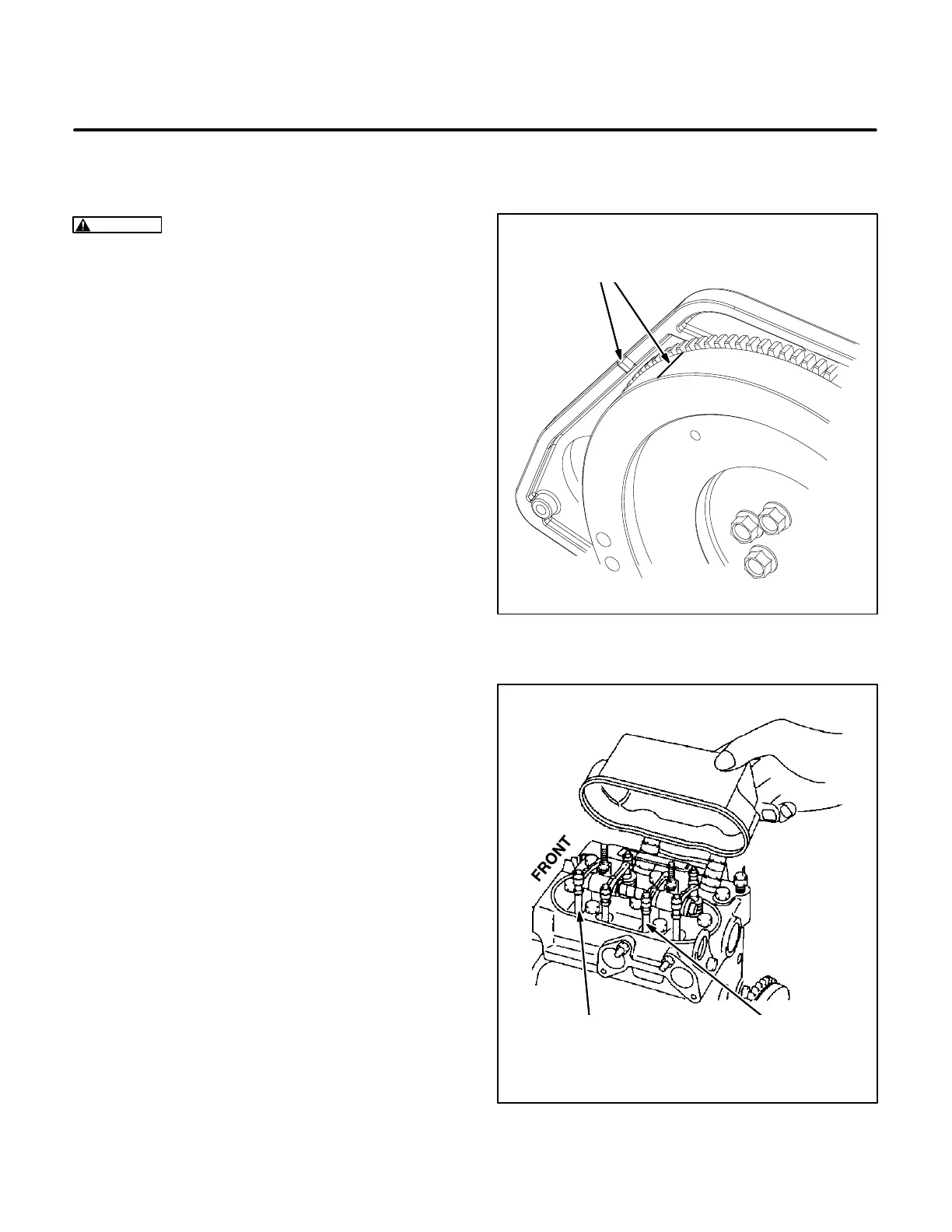
Adjusting Valve Lash: Do not use the fuel injection
timing marks (Figure 6-1) when adjusting valve
lash. Using them could lead to misadjustments.
Valve lash should be adjusted when both valves are
closed at TDC for the cylinder power stroke (every
other revolution). To locate this position for either
cylinder, rotate the engine clockwise (looking from
the front) until the intake valve push rod (Figure 6-2)
just stops moving down (valve closed). Then turn
the engine one half turn more and adjust lash for
both valves (intake and exhaust). Repeat this pro-
cedure for the other cylinder. Adjust valve lash to
0.0059–0.0073 inch (0.145–0.185 mm).
The rocker arm cover is accessible through the top
access opening (Page 5-1). To get the rocker arm
cover off, remove the screw that secures the intake
resonator (Figure 6-3) to the cover and tilt the reso-
nator out of the way. Also remove the glow plugs.
LINE UP THESE MARKS
WHEN SETTING FUEL
INJECTION TIMING
FIGURE 6-1. FUEL INJECTION TIMING MARKS
PUSH ROD,
CYL #2
INTAKE VALVE
PUSH ROD,
CYL #1
INTAKE VALVE
FIGURE 6-2. ROCKER ARMS AND PUSH RODS
Redistribution or publication of this document,
by any means, is strictly prohibited.

 Loading...
