8-5
TESTING GENERATOR WINDINGS
Testing the Rotor
Field Resistance Test: Disconnect field leads F1
and F2 from controller A1 by pulling green connec-
tor P3 and measure resistance across pins 7 and 8.
If resistance is not as specified in Table 8-1:
1. Check for and repair faulty field leads.
2. Service brush block and slip rings (Page 8-4).
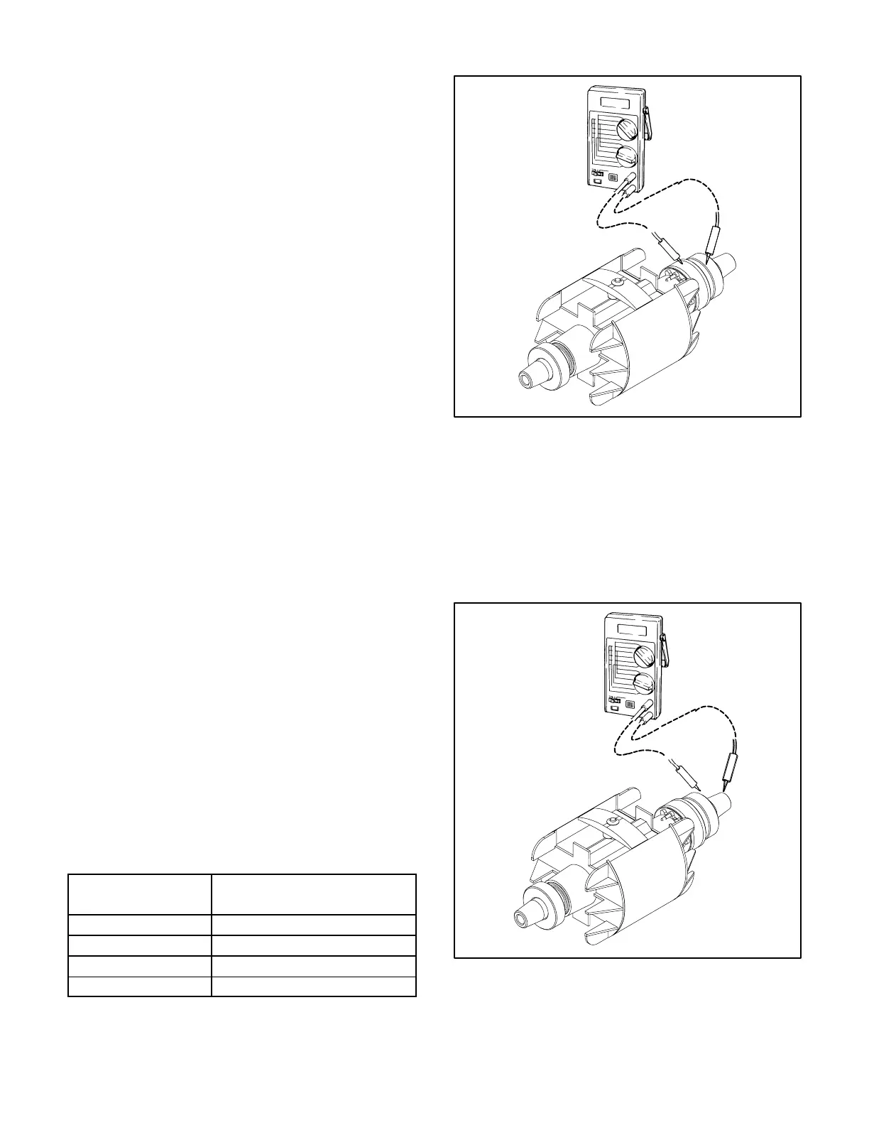
3. Check rotor resistance across the slip rings
(Figure 8-3). Replace the rotor if resistance is
not as specified.
Ground Test: Using a megger or the highest scale
on a digital ohmmeter, measure resistance between
the rotor and either slip ring (Figure 8-4). Replace
the rotor if its winding has less than one megohm re-
sistance to ground.
Testing the Stator
Disconnect T1, T2, T3 and T4 from the terminals in
the output box. Disconnect B1 and B2 from charging
regulator AVR1 (Figure 9-1). Disconnect Q1 and Q2
from controller A1 by pulling green connector P3
(Pins 4 and 5).
Open Winding Test: Measure resistance across
each winding lead pair (Table 8-1). Replace the sta-
tor if any winding is open (zero ohms).
Winding Resistance Test: Use a meter (Wheat-
stone Bridge) having 0.001 ohm precision to mea-
sure resistance across each winding lead pair
(Table 8-1). Replace the stator if resistance in any
winding is not as specified.
Ground Test: Using a megger or the highest scale
on a digital ohmmeter, measure resistance between
the stack and each stator lead. Replace the stator if
any winding has less than one megohm resistance
to ground.
TABLE 8-1. GENERATOR WINDING RESISTANCES
Winding
Resistance (Ohms)
@ 775 F (255 C) + 10%
T1–T2, T3–4 0.353
Q1–Q2 2.93
B1–B2 0.114
F1–F2 32
FIGURE 8-3. OPEN OR SHORTED ROTOR TEST
FIGURE 8-4. GROUNDED ROTOR TEST
Redistribution or publication of this document,
by any means, is strictly prohibited.

 Loading...
