COOLING
SYSTEM
A
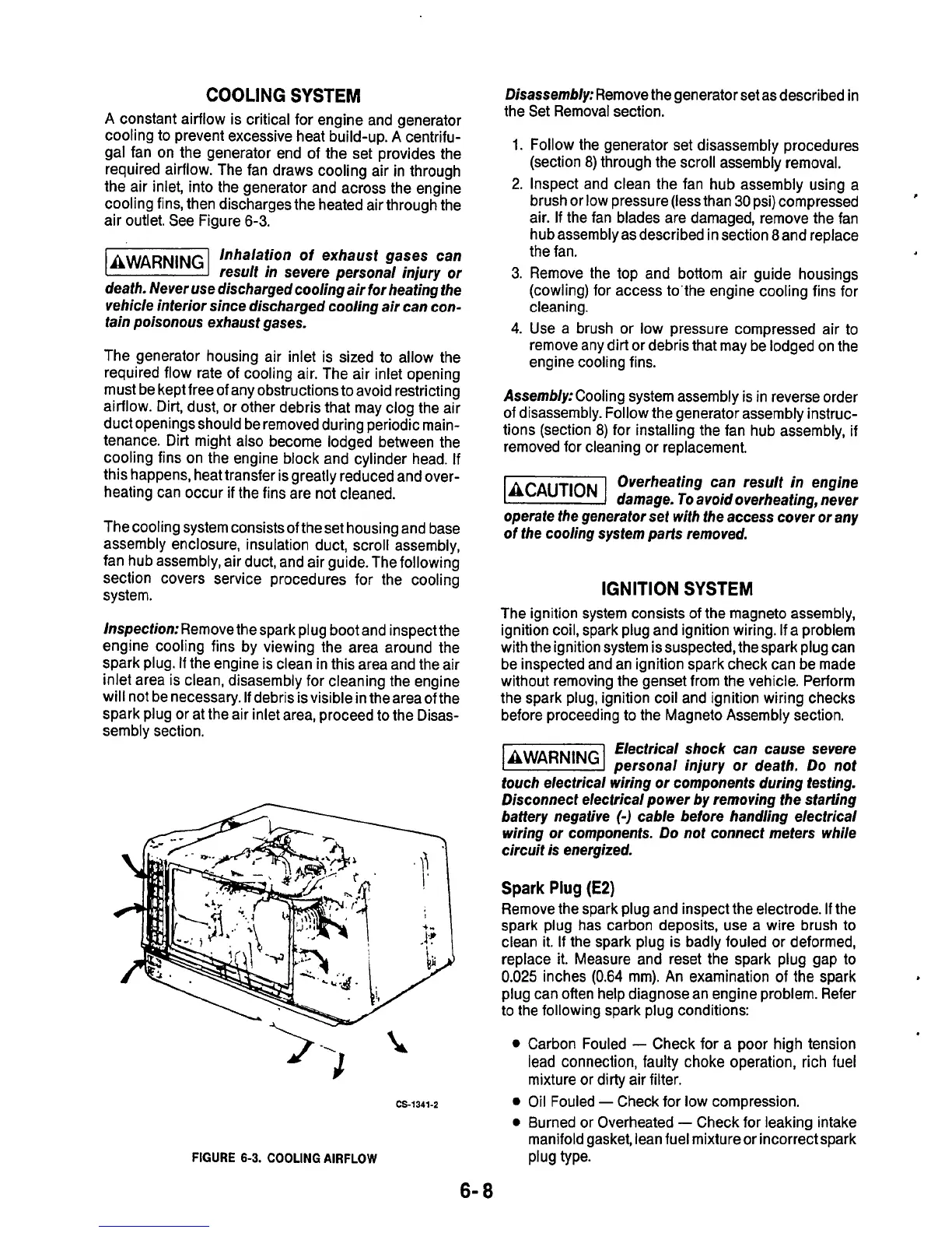
constant airflow is critical for engine and generator
cooling to prevent excessive heat build-up.
A
centrifu-
gal fan on the generator end of the set provides the
required airflow. The fan draws cooling air in through
the air inlet, into the generator and across the engine
cooling fins, then discharges the heated air through the
air outlet. See Figure
6-3.
Inhalation of exhaust gases can
EiEEEGI
result in severe personal injury
or
death. Never use discharged cooling air for heating the
vehicle interior since discharged cooling air can con-
tain poisonous exhaust gases.
The generator housing air inlet is sized to allow the
required flow rate of cooling air. The air inlet opening
must be kept free of any obstructions to avoid restricting
airflow. Dirt, dust, or other debris that may clog the air
duct openings should be removed during periodic main-
tenance. Dirt might also become lodged between the
cooling fins on the engine block and cylinder head.
If
this happens, heat transfer is greatly reduced and over-
heating can occur
if
the fins are not cleaned.
The cooling system consists of the set housing and base
assembly enclosure, insulation duct, scroll assembly,
fan hub assembly, air duct, and air guide. The following
section covers service procedures for the cooling
system.
Disassembly:
Remove the generator set as described in
the Set Removal section.
1.
2.
3.
4.
Follow the generator set disassembly procedures
(section 8) through the scroll assembly removal.
Inspect and clean the fan hub assembly using a
brush or low pressure (less than
30
psi) compressed
air.
If
the fan blades are damaged, remove the fan
hub assembly as described in section 8and replace
the fan.
Remove the top and bottom air guide housings
(cowling) for access to’the engine cooling fins for
cleaning.
Use a brush or low pressure compressed air
to
remove any dirt or debris that may be lodged on the
engine cooling fins.
?
1nspection:Remove
the spark plug boot and inspect the
engine cooling fins by viewing the area around the
spark plug.
If
the engine is clean in this area and the air
inlet area is clean, disasembly for cleaning the engine
will not be necessary.
If
debris is visible in the area of the
spark plug or at the air inlet area, proceed
to
the Disas-
sembly section.
Spark
Plug
(E2)
Remove the spark plug and inspect the electrode.
If
the
spark plug has carbon deposits, use a wire brush
to
clean
it.
If
the spark plug is badly fouled or deformed,
replace it. Measure and reset the spark plug gap
to
0.025
inches
(0.64
mm). An examination of the spark
plug can often help diagnose an engine problem. Refer
to the following spark plug conditions:
.
Assembly:
Cooling system assembly is in reverse order
of disassembly. Follow the generator assembly instruc-
tions (section 8) for installing the fan hub assembly, if
removed for cleaning or replacement.
Overheating can result in engine
damage.
To
avoid overheating, never
operate the generator set with the access cover
or
any
of
the cooling system parts removed.
IGNITION
SYSTEM
The ignition system consists of the magneto assembly,
ignition coil, spark plug and ignition wiring.
If
a problem
with the ignition system issuspected, the spark plug can
be inspected and an ignition spark check can be made
without removing the genset from the vehicle. Perform
the spark plug, ignition coil and ignition wiring checks
before proceeding to the Magneto Assembly section.
Electrical shock can cause severe
personal injury or death. Do not
touch electrical wiring
or
components during testing.
Disconnect electrical power by removing the starting
battery negative
(-1
cable before handling electrical
wiring
or
components. Do not connect meters while
circuit is energized.
>
-----
t
CS-1341-2
FIGURE
6-3.
COOLING
AIRFLOW
Carbon Fouled
-
Check for a poor high tension
lead connection, faulty choke operation, rich fuel
mixture or dirty air filter.
Oil Fouled
-
Check for low compression.
Burned or Overheated
-
Check for leaking intake
manifold gasket, lean fuel mixture or incorrect spark
Plug type-
6-
8

 Loading...
