Careless handling of the stator can
damage the insulation
on
the stator
windings.
Do
Not brush windings against the hous-
ing or strike windings during installation.
5.
Align slot in rotor shaft with Woodruff key on crank-
shaft and lower rotor onto crankshaft. Make sure
that the rotor is seated.
Misalignment
of
the rotor shaft
and the crankshaft can cause
damage to the rotor and stator assembly.Use care
when installing the rotor shaft
to
align the crank-
shaft and rotor shaft with the Woodruff key in the
crankshaft.
6. Attach the stator wire harness connectors
to
the
stator. Be careful not
to
bend connector terminals or
damage may occur. Refer to Figures 8-1 and
8-2
for
wiring locations. Use wire ties
to
secure stator leads
away from rotor and fan hub
to
prevent rubbing.
7.
Prepare endbell for installation. Place springs on
studs and lubricate O-ring. Verify that brushes are
held in holder with piece of wire. See Figure 8-6.
Install endbell onto rotor bearing and secure with
endbell mounting screws.
The brushes will be damaged
@@%@I
during assembly if not held
off
the slip rings. Make certain wire is in place before
installing the generator endbell.
8. Remove the piece
of
wire holding the brushes
off
the slip rings. Connect the F- lead wire
to
the
out-
board brush terminal and the F+ lead wire to the
inboard brush terminal.
9.
Install fan hub onto rotor shaft and align key slot on
fan hub with key slot in end
of
rotor shaft. Install
alignment key. Insert washer on rotor through-bolt
and install into rotor shaft. Verify alignment of rotor
shaft and fan hub. Use special tool
to
secure fan hub
assembly (Figure
8-4)
and tighten the rotorthrough-
bolt
to
the specified torque.
Leaking fuel will create a fire
hazard which can result in.
severe personal injury or death.
If
leaks are
detected correct immediately. Replace worn fuel
line components before leaks occur.
15.
Connect the
B+
lead to the start solenoid. Attach
K3
relay
to
the inlet baffle assembly (Figure
7-3).
16.
Install the control panel. Inspect assembly, check all
electrical and mechanical connections for correct
fit and location. Place enclosure cover on set and
secure with side mounting screws.
17.
Install the generator set in the vehicle and securely
fasten all mounting screws and hardware. Connect
the fuel line, exhaust system and electrical systems
in reverse order
of
disassembly. Refer
to
Set Remo-
val (section
5).
18.
Fill crankcase with oil of the recommended classifi-
cation and viscosity.
BRUSHES
AND
SLIP
RINGS
This section covers brush replacement and slip ring
service.
Brush
Replacement
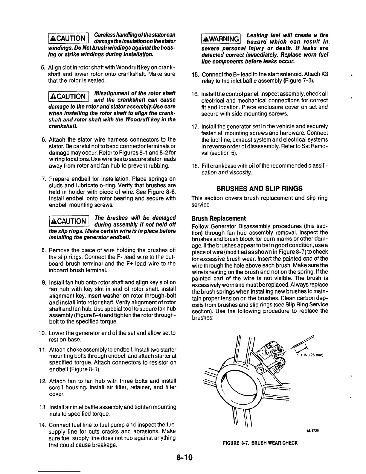
Follow Generator Disassembly procedures (this sec-
tion) through fan hub assembly removal. Inspect the
brushes and brush block for burn marks or other dam-
age.
If
the brushes appear
to
be in good condition, use a
piece
of
wire (modified as shown in Figure
8-7)
to check
for
excessive brush wear. Insert the painted end
of
the
wire through the hole above each brush. Make sure the
wire is resting on the brush and not on the spring.
If
the
painted part of the wire is not visible. The brush is
excessively worn and must be replaced. Always replace
the brush springs when installing new brushes
to
main-
tain proper tension on the brushes. Clean carbon dep-
osits from brushes and slip rings (see Slip Ring Service
section). Use the following procedure
to
replace the
brushes:
10. Lower the generator end
of
the set and allow set to
rest on base.
11.
Attach choke assembly
to
endbell. Install two starter
mounting
bolts
through endbell and attach starter at
specified torque. Attach connectors
to
resistor on
endbell (Figure
8-1).
12.
Attach fan
to
fan hub with three bolts and install
scroll housing. Install air filter, retainer, and filter
cover.
13.
Install air inlet baffle assembly and tighten mounting
14.
Connect fuel line to fuel pump and inspect the fuel
sure fuel supply line does not rub against anything
that
could cause breakage.
nuts
to
specified torque.
supply line for cuts cracks and abrasions. Make
M-1729
FIGURE
8-7.
BRUSH
WEAR
CHECK
8-1
0

 Loading...
