LPG
FUEL
SYSTEM
The LPG-fueled models use a low-pressure vapor
withdrawal system that must be properly adjusted and
be in good working condition. Components unique
to
the fuel system are:
Demand Regulator with Automatic Priming
Solenoid
0
LPG Carburetor
0
Fuel Solenoid
Special precautions must be taken to avoid releasing
large quantities of highly flammable
LP
gas when servic-
ing the fuel system. Use the LP gas purging procedure
described in the
Preparing
to
Service
section
to
purge
the fuel system of LP gas before servicing any fuel
system components.
The fuel supply line pressure to the demand regulator must be in the
range
of
6
to
B
ounces per square inch
(10
to
14
inches
of
water
column).
The fuel supply line from the primary regulator to the
generator set fuel system components must be dedi-
cated
to
the generator set only and not shared with any
appliances.
[-I
LP gas presents the hazard of fire
or
explosion and
it
is poisonous. These
hazards can result in severe personal injury
or
death. If
flameout occurs with an unvented appliance, LP gas
can accumulate inside the vehicle and create a safety
hazard. If the generator set tuel supply line
is
shared
with any appliance, do not continue with any further
service procedures. Correct as necessary to comply
with applicable codes before continuing service
work.
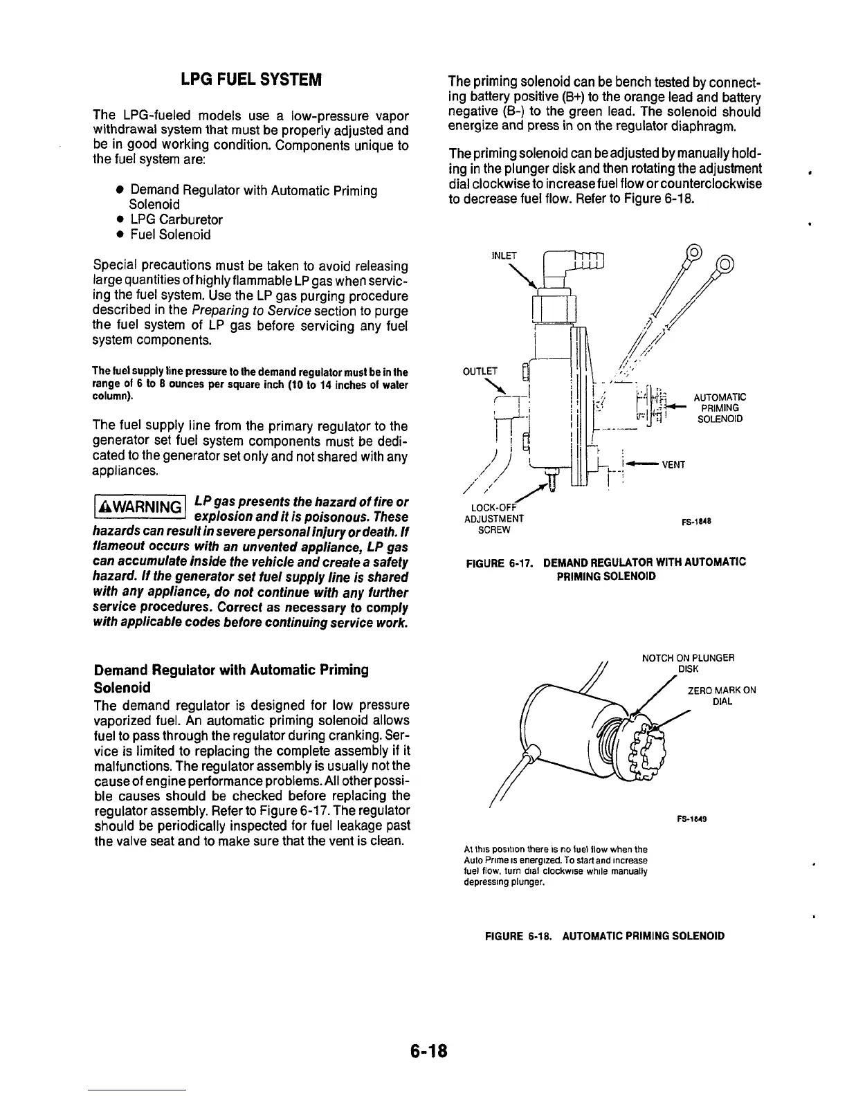
Demand
Regulator with Automatic Priming
Solenoid
The demand regulator is designed for low pressure
vaporized fuel. An automatic priming solenoid allows
fuel to pass through the regulator during cranking. Ser-
vice
is
limited to replacing the complete assembly
if
it
malfunctions. The regulator assembly is usually not the
cause
of
engine performance problems.
All
other possi-
ble causes should be checked before replacing the
regulator assembly. Refer to Figure
6-17.
The regulator
should be periodically inspected for fuel leakage past
the valve seat and to make sure that the vent is clean.
The priming solenoid can be bench tested by connect-
ing battery positive
(B+)
to
the orange lead and battery
negative
(B-)
to the green lead. The solenoid should
energize and press in on the regulator diaphragm.
The priming solenoid can be adjusted by manually hold-
ing in the plunger disk and then rotating the adjustment
dial clockwise
to
increase fuel flow or counterclockwise
to decrease fuel flow. Refer
to
Figure
6-18.
OUTLET
D
I
AUTOMATIC
PRIMING
I
VENT
ADJUSTMENT
SCREW
Fs-1848
FIGURE
6-17.
DEMAND
REGULATOR
WITH
AUTOMATIC
PRIMING
SOLENOID
NOTCH ON PLUNGER
ZERO MARK
ON
DIAL
FS-1849
At this position there
is
no
iuel
flow
when
the
Aulo
Prime is energized.
To
start and increase
iuel flow.
turn
dial clockwise while manually
depressing plunger.
FIGURE
6-18.
AUTOMATIC
PRIMING
SOLENOID
6-1
8

 Loading...
