GENERATOR SERVICE
This section covers generator disassembly and assem-
bly procedures.
Refer
to
Figure 8-3
to
identify
the
var-
ious generator components described in each sub-
section.
Generator
Disassembly
Use the following procedures to disassemble the
generator:
1.
2.
3.
4.
5.
6.
7.
Drain the engine
oil
while the generator set
is
still
mounted in the vehicle.
Hot oil can cause severe burns if
k&@!%l
spilled or splashed on skin.
Keep hands clear when removing oil drain plug and
wear protective clothing.
Remove the generator set from the vehicle and
place
it
on a sturdy workbench. Refer
to
Set Remo-
val (section
5)
for the recommended set removal
procedures.
The generator set is heavy and
lgWARNlNGl
can result in severe personal
injury if dropped during removal. Use the recom-
mended removal techniques and keep hands and
feet clear while removing mounting bolts.
Remove side mounting screws from enclosure
cover
and
lift
cover
off
set.
Disconnect the fuel line from the fuel pump. Plug
fuel lines
to
keep fuel from escaping.
Fuel presents the hazard
of
fire
or explosion which can cause
severe personal injury or death.
Do
not permit any
flame, spark, pilot light, cigarette, or other ignition
source near the generator set. Keep a type
ABC
fire
extinguisher nearby.
Remove the
K3
relay from the inlet baffle assembly
(Figure 7-2). Disconnect the
B+
lead from the start
solenoid.
Remove the control panel mounting screws and
lower the control panel.
Remove the two bottom mounting nutssecuring the
inlet baffle assembly. Lift the inlet baffle up and
move it to the right side.
,..a.
FAN
HUE
.
-1.
.
.-.
FIGURE
8-4.
SECURING FAN HUB
ASSEMBLY FOR REMOVAL
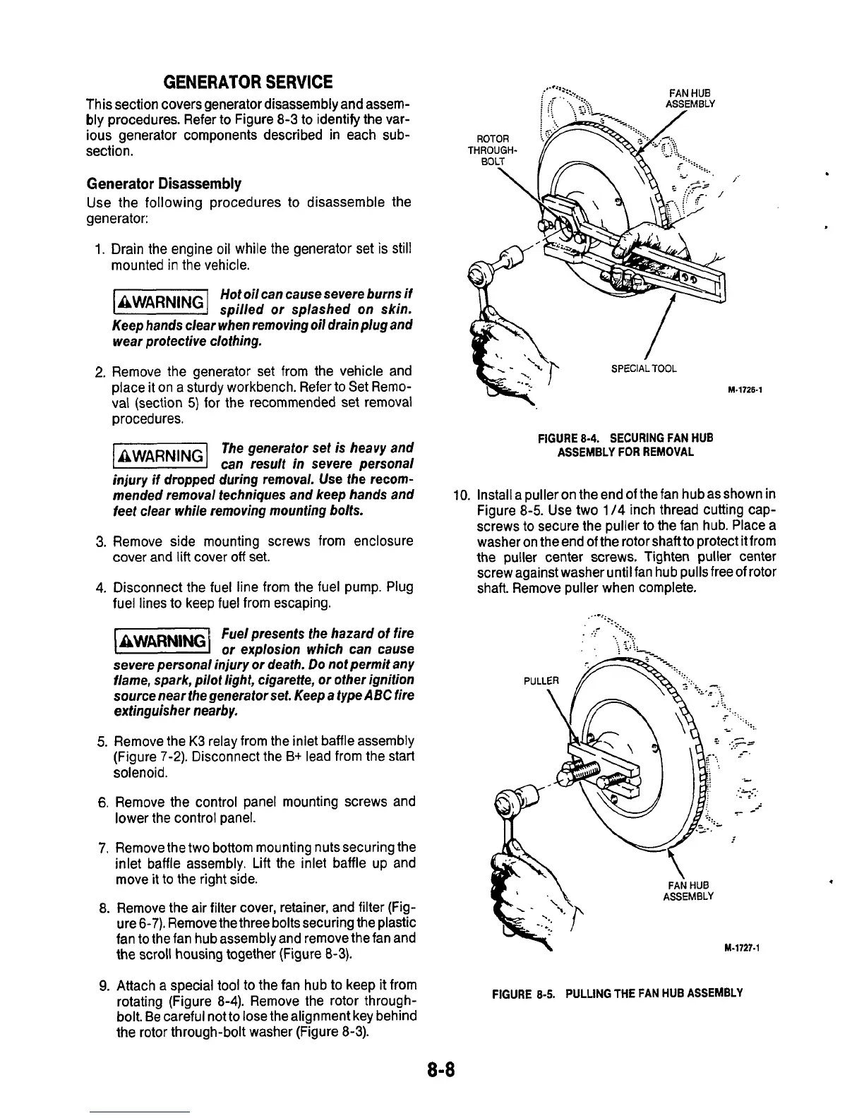
10.
Installa pulleron theendofthefan hubasshownin
Figure
8-5.
Use two
1
/4
inch thread cutting cap-
screws
to
secure the puller
to
the fan hub. Place a
washer on the end
of
the rotor shaftto protect it from
the puller center
screws.
Tighten puller
center
screwagainst washer until fan hub pullsfreeof rotor
shaft. Remove puller when complete.
ASSEMBLY
8. Remove the air filter cover, retainer, and filter (Fig-
ure 6-7). Remove the three boltssecuring the plastic
fan
to
the fan hub assembly and remove the fan and
the scroll housing together (Figure
8-3).
9.
Attach a special
tool
to the fan hub to keep
it
from
rotating (Figure 8-4). Remove the rotor through-
bolt.
Be
careful not to lose thealignment key behind
the rotor through-bolt washer (Figure 8-3).
M-1727.1
FIGURE
8-5.
PULLING
THE
FAN
HUB ASSEMBLY
8-8
.

 Loading...
