Assembly
Torques
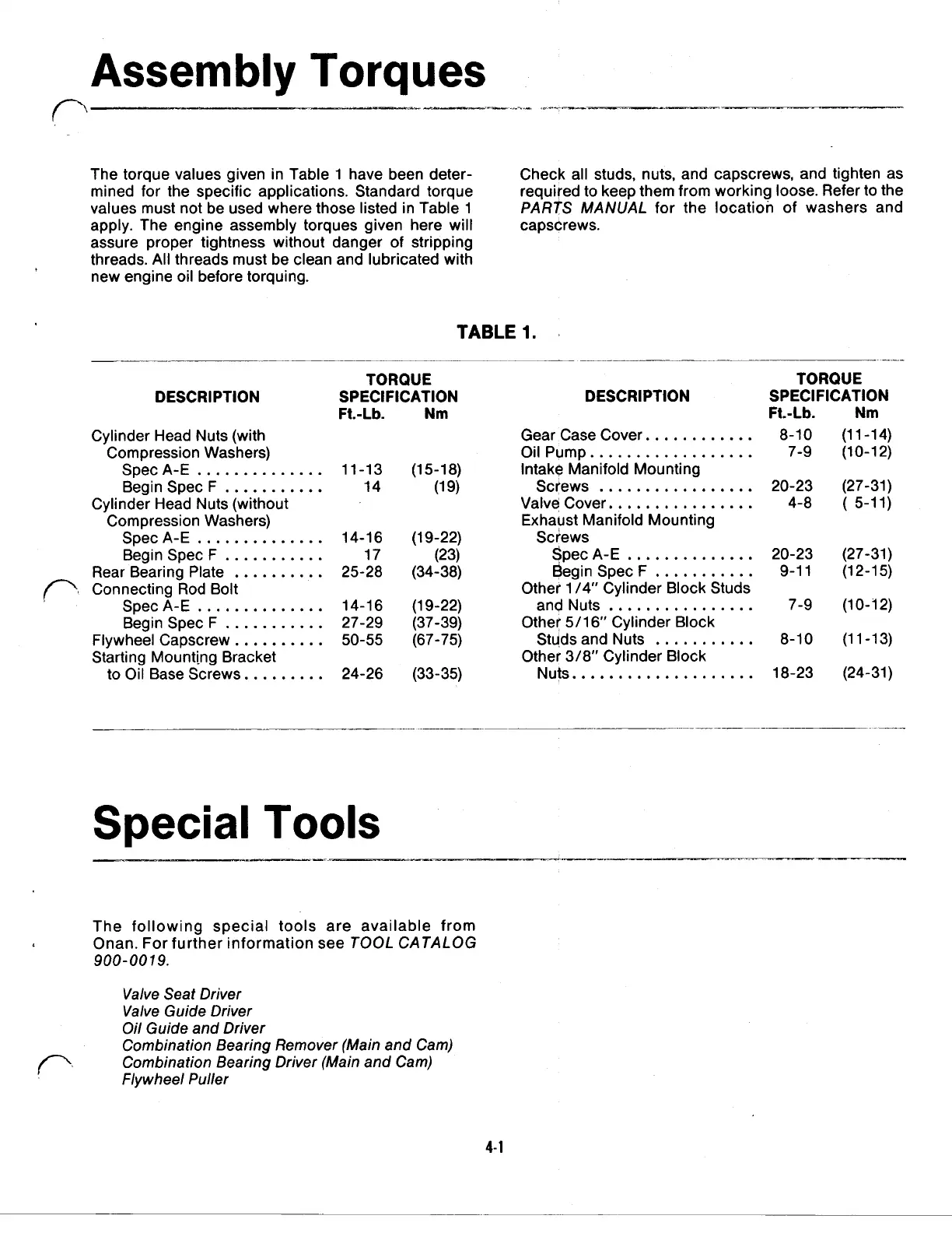
The torque values given in Table 1 have been deter- Check all studs, nuts, and capscrews, and tighten as
mined for the specific applications. Standard torque required to keep them from working loose. Refer to the
values must not be used where those listed in Table
1
PARTS MANUAL
for the location
of
washers and
apply. The engine assembly torques given here will capscrews.
assure proper tightness without danger
of
stripping
threads.
All
threads must be clean and lubricated with
new engine oil before torquing.
DESCRIPTION
Cylinder Head Nuts (with
Compression Washers)
SpecA-E
Begin Spec F
Cylinder Head Nuts (without
Compression Washers)
SpecA-E
Rear Bearing Plate
Connecting Rod Bolt
SpecA-E
Begin Spec F
Flywheel Capscrew.
Starting Mounting Bracket
to Oil Base Screws.
Begin Spec F
TABLE
1.
TORQUE
SPECIFICATION DESCRIPTION
F1.-Lb. Nm
Gear Case Cover.
Oil Pump.
14
Valve Cover.
Exhaust Manifold Mounting
11-13 (15-18) Intake Manifold Mounting
(19) Screws
14-16 (19-22) Screws
17
25-28 (34-38) Begin Spec F
Other 1/4” /4" Cylinder Block Studs
(23) Spec
A-E
14-16 (1 9-22)
and Nuts
27-29 (37-39)
Other 5/16" Cylinder Block
50-55 (67-75)
Studs and Nuts
24-26 (33-35) Nuts.
Other 3/8” Cylinder Block
TORQUE
SPECIFICATION
F1.-Lb. Nm
8-10 (1 1-14)
7-9 (10-1 2)
(27-31)
4-8
(
5-11)
20-23
(27-31)
9-11
(12-15)
7-9 (10-72)
8-10 (1 1-13)
18-23 (24-31)
Special
Tools
The following special tools are available from
Onan. For further information see
TOOL CATALOG
900-0019.
Valve Seat Driver
Valve Guide Driver
Oil Guide and Driver
Combination Bearing Remover (Main and Cam)
Combination Bearing Driver (Main and Cam)
Flywheel Puller
4-1
 Loading...

