Apply a thin film of oil to the gasket. Spin element down
by hand until gasket just touches mounting pad and
then turn down an additional
1/2-3/4
turn.
Do
not
overtighten.
With oil in crankcase, start engine and check for leaks
around filter element. Retighten only as much as
necessary to eliminate leaks; do not overtighten.
CRANKCASE BREATHER
The crankcase breather prevents pressure from
building up in the crankcase. It also prevents oil
contamination by removing moisture or gasoline
vapors and other harmful blow-by materials from the
crankcase. Thesevapors are routed to the carburetor
where they are mixed with incoming air and burned in
the combustion chamber.
A
sticky breather valve can
cause leaks, high oil consumption, rough idle,
reduced engine power and a rapid formation of
sludge and varnish within the engine.
Crankcase Breather Service
This engine uses. a crankcase breather valve for
maintaining crankcase vacuum. If the crankcase
becomes pressurized as evidenced by oil leaks at the
seals, clean baffle and valve in a suitable solvent.
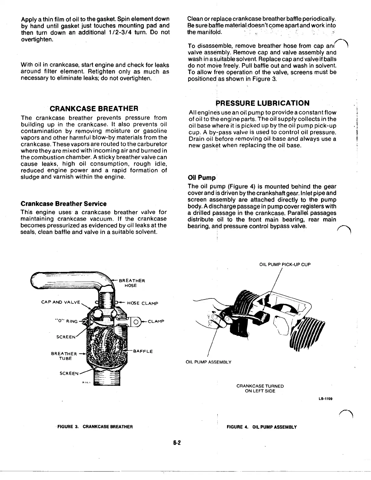
BREATHER
HOSE
CAP AND VALVE
HOSE
CLAMP
FIGURE
3.
CRANKCASE BREATHER
Clean or replace crankcase breather baffle periodically.
Be sure baffle material-doesn’t come apart and work into
the manifold.
To disassemble, remove breather hose from cap and
valve assembly. Remove cap and valve assembly and
wash in a suitable solvent. Replace cap and valve if balls
do not move freely. Pull baffle out and wash in solvent.
To
allow free operation of the valve, screens must be
positioned as shown in Figure
3.
PRESSURE LUBRICATION
All
engines use an oil pump to provide a constant flow
of oil to the engine parts. The oil supply collects in the
oil base where it is picked up by the oil pump pick-up
cup.
A
by-pass valve is used to control oil pressure.
Drain oil before removing oil base and always use a
new gasket when replacing the oil base.
Oil
Pump
The oil pump (Figure
4)
is mounted behind the gear
cover and is driven by the crankshaft gear. Inlet pipe and
screen assembly are attached directly to the pump
body. A discharge passage in pump cover registers with
a drilled passage in the crankcase. Parallel passages
distribute oil to the front main bearing, rear main
bearing, and pressure control bypass valve.
OIL
PUMP PICK-UP CUP
OIL PUMP ASSEMBLY
CRANKCASETURNED
ON LEFT SIDE
FIGURE
4.
OIL
PUMP
ASSEMBLY
6-2
LS-1109
 Loading...

