CYLINDER HEAD STUD TEST
AND REPLACEMENT PROCEDURE
This cylinder head stud replacement procedure should
be used whenever replacing any of the top six studs on
the block. The use of Helicoil is not a recommended
repair procedure.
If
a Helicoil has been used, the
cylinder block must be replaced. Graphoil head and
intake manifold gaskets should also be used when
replacing cylinder head studs.
Parts
Required
Part
No.
Description
520-091 2 Step stud
1
10-2987 Head gasket
154-221
9
Intake manifold gasket
420-0398 Drilling fixture (Reusable tool)
1.
Disconnect the spark plug wires and remove the
spark plugs and cylinder head air shrouds from
each cylinder.
2.
Remove the nuts and compression washers (do not
remove the flatwashers) from the top six studs on
each cylinder head (Figure 30). Each stud will have
two compression washers and one flatwasher
arranged in the sequence shown
in
Figure 31.
Do
not remove the nuts from the bottom four studs
before the test procedure is completed.
USE
STUDS
SHOWN
ABOVE
LINE
FOR
SECTION
1
STUD
TEST
LEFT CYLtNDER
RIGHT
CYLINDER
NUMBERS
INDICATE CORRECT
TIGHTENING
SEQUENCE
FOR
CYLINDER
HEAD
NUTS
FIGURE
30.
CYLINDER HEADS
-10-18
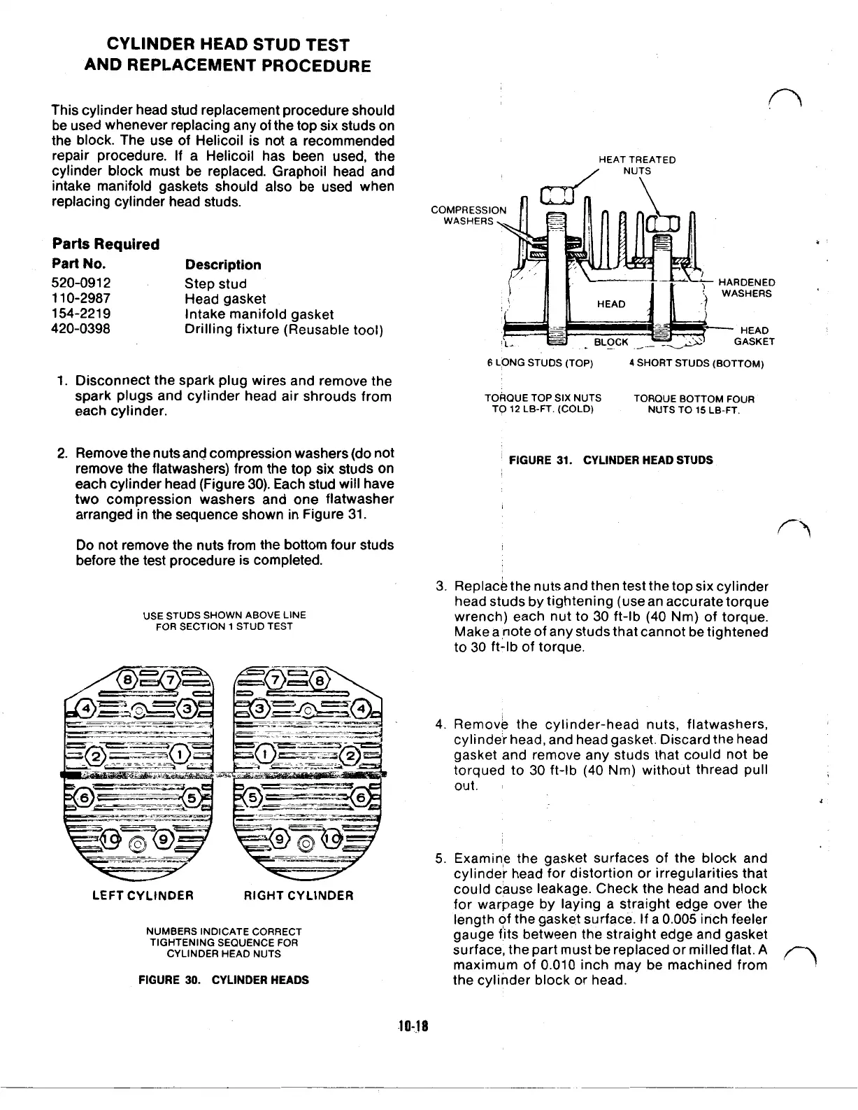
HEAT
TREATED
NUTS
COMPRESSION
WASHERS
HARDENED
WASHERS
HEAD
GASKET
6
LONG
STUDS
(TOP)
4
SHORT STUDS
(BOTTOM)
TORQUE
TOP
SIX
NUTS
TORQUE
BOTTOM
FOUR
TO
12
LB-FT.
(COLD)
NUTS
TO
15
LB-FT.
FIGURE
31.
CYLINDER HEAD STUDS
3. Replace the nuts and then test the top six cylinder
head studs by tightening (use an accurate torque
wrench) each nut to 30 ft-lb (40 Nm) of torque.
Make a note of any studs that cannot be tightened
to 30 ft-lb of torque.
4.
Remove the cylinder-head nuts, flatwashers,
cylinder head, and head gasket. Discard the head
gasket and remove any studs that could not be
torqued
to
30 ft-lb
(40
Nm) without thread pull
out.
5.
Examine the gasket surfaces of the block and
cylinder head for distortion or irregularities that
could cause leakage. Check the head and block
for warpage by laying a straight edge over the
length of the gasket surface. If a
0.005
inch feeler
gauge fits between the straight edge and gasket
surface, the part must be replaced or milled flat.
A
maximum of 0.010 inch may be machined from
the cylinder block or head.
 Loading...

