9
Getting to Know the Receiver—Continued
U STANDBY indicator (22)
Lights up when the receiver is on Standby and
flashes while a signal is being received from the
remote controller.
V PHONES jack (24)
This 1/4-inch phone jack is for connecting a
standard pair of stereo headphones for private
listening.
A REMOTE CONTROL jack
This (Remote Interactive) jack can be
connected to the jacks on your other Onkyo
audio components. The receiver’s remote controller
can then be used to control all of your components.
To use , you must make an analog audio
connection between the receiver and each component.
B MONITOR OUT
This jack is for connecting a TV with a composite
video output.
C AM ANTENNA
These push terminals are for connecting an AM
antenna.
D XM antenna (North American model only)
This jack is for connecting a satellite radio such as
the XM Mini-Tuner System, sold separately.
E FM ANTENNA
This jack is for connecting an FM antenna.
F SIRIUS antenna (North American model
only)
This jack is for connecting a SIRIUS digital
antenna, sold separately (see the separate SIRIUS
instructions).
G IR IN/OUT
A commercially available IR receiver can be
connected to the IR IN jack, allowing you to control
the receiver while you’re in Zone 2, or control it
when it’s out of sight, for example, installed in a
cabinet.
A commercially available IR emitter can be
connected to the IR OUT jack to pass IR (infrared)
remote control signals along to other components.
H PRE OUT: L/R, SUBWOOFER
This analog audio output can be connected to the
analog audio input on a power amplifier when you
want to use the receiver solely as a preamplifier. The
SUBWOOFER jack is for connecting a powered
subwoofer.
I ZONE 2 PRE OUT L/R
These analog audio outputs can be connected to the
line inputs on amplifiers in Zone 2.
J AC OUTLET
This switched AC outlet can be used to supply
power to another component. The type of outlet
depends on the country in which you purchased
your receiver.
K PHONO (MM) input and grounding terminal
This analog audio input is for connecting a turntable
with a moving-magnet cartridge. The screw located
on the upper-left of the PHONO (MM) inputs is for
connecting a turntable’s ground wire.
L CD input
This analog audio input is for connecting a CD
player’s analog audio output.
M TAPE IN/OUT
This analog audio input and output are for
connecting a recorder with an analog audio input
and output, such as a cassette deck, MD recorder,
etc.
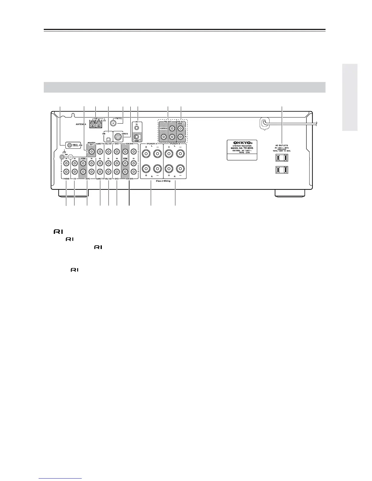
Rear Panel
KL M N O P Q R S
1 4 6 9 J
B
5
3 7 8
 Loading...