Setting up your Bicycle
Now that you have opened the box and unpacked your new bike – How do you get this thing
working?! Please follow the instructions and suggestions given in this chapter carefully, to
ensure you can start off your recumbent cycling addiction safely and securely.
Assembling from the Box
Your bike will arrive partially or fully assembled, depending on where you live. Now all you need
to do is follow the following steps in the order written, and you’ll be riding your recumbent in no
time! Some steps will only apply to certain models, in which case this will be clearly stated.
1. Installing the wheels.
For ease in construction and accessibility it is best to start by mounting the wheels. Optima
bikes come with either bolt on or quick release wheel fastenings, depending on the model
and specications.
The rear wheel is fastened using a quick release lever for standard
hubs and bolts for SRAM’s dual drive or 3x7 derailleur/hub gear
systems.
When removing or replacing any rear wheel, make sure the chain is
fed properly around the cogs on the wheel, as seen in gure 6.1.
Quick release fastening allow for fast installation and
removal of the wheels. Properly fastened quick release
wheels are in no way less safe than bolted wheels.
To install the wheel, simply pull the lever on the wheel
outward to the unlocked position (g 6.3). After unlocking
the mechanism, feed the wheel into the forks or the frame.
Ensure that the wheel is fully inserted in the frame, to prevent
the brakes dragging on the rim or disk. If the brakes drag
when the wheel is properly inserted, readjust the brakes.
Now press the lever to the closed position, as seen in gure
6.2. (The nut on the opposite side to the lever may need to
be tightened or loosened to allow for the closure of the lever
to clamp the forks properly). To remove the wheel, unlock the wheel by pulling the lever. You
may need to unscrew the bolt on the opposite side slightly to get the quick release skewer past
safety knobs on the dropouts. If you are not already experienced in the use of quick release
skewers, see the manufacturer’s procedures in the enclosed information package for proper
use. Otherwise ask the sales representative or a local bicycle store for assistance.
Warning! An improperly fastened quick release lever could lead
to the dislodging of the wheel during braking, leading to serious
injury and damage to your bicycle.
6
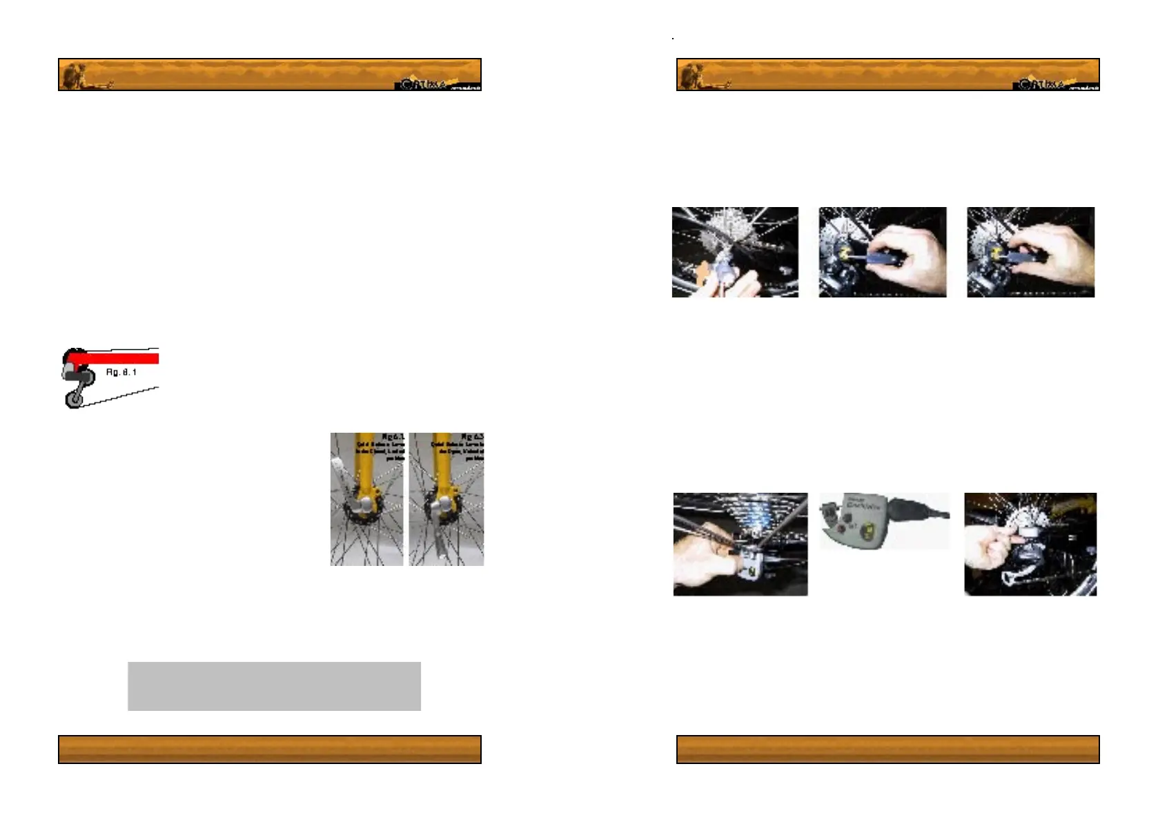
3x7 derailleur and hub gear system Installation and removal.
To install (or remove) the rear 3x7 wheel, rst put the left handlebar shifter to the lowest gear
(position on the grip 1). Feed the wheel into the frame ensuring that the cog cassette is on the
right hand side of the wheel, the same side as the rear derailleur. Now bolt the wheel to the
frame, using a 15 mm metric spanner. Once the wheel has been fastened, feed the shifting
linkage chain into the gear shifting roller and slide the shifting roller onto the hub axle stub
(g 7.1). You will hear and feel a positive click when it is properly engaged. Now track the link
chain around the roller.
The next step is to connect the shifting chains threaded stub with the shifting cable connection
unit. This is done easily, by simply feeding the stub into the unit, as seen in images 7.2 and 7.3.
Feed the connector unit onto the stub to the point at which most of the slack is gone from the
shifting cable and release the block. Now check that the handlebar shifter units can engage
all three gears. If the top gear cannot be engaged, you will need to loosen the connector unit
and allow a little more slack in the cable.
To move or remove the connection unit from the shifting chain stub you will need to pinch
the unit at it’s end, pressing the small square plate of brass in to release the ratchets which
prevent the unit from slipping (see g 7.2) To clamp the unit to the stub again, simply release
the button
7
Dual Drive derailleur and hub shifting system wheel installation and removal.
The hub will need to be bolted onto the frame using a 15mm spanner. Once bolted on you can
install the gear shifting linkage unit.
Start by putting the thumb lever on the handlebar shifting unit to the leftmost setting, with one
dot. When you look at the hub connection unit, the yellow indicator in the small window should
be as close to the axle hole as possible, (g.7.5). Next, you will need to press the black shaft
sticking out of the top of the connection unit in fully so that it sticks out of the bottom of the
unit. This will not be possible if the thumb shifter is not in position 1.
 Loading...