2. Installing linkage front steering systems 10.4
Setting up the steering linkage (All 2 and 3 wheel linkage steering models)
You will now need to connect the master to slave steering linkage. This may have already been
done, depending on where you live. You may however need to disconnect and connect the
linkage at some time anyway. To disconnect the linkage, pull the safety pin off the shaft (gs 8.2
and 8.3) and pull it out of the hole at the foot of the socket and shaft (g 10.4). To (re)connect
the linkage, make sure the safety pin is removed. Then push the linkage’s socket onto the
slave joint ball (seen bare in g 10.5) Once the socket is correctly around the ball joint, you will
be able to slide the safety pin back into the socket’s ange (g 10.7). If the pin will not go in,
the socket is not properly on the ball joint. This may require some force. If you cannot do it by
hand, give the socket moderated a tap with a rubber mallet to connect the joint properly. Once
properly on the ball joint, (Fig 8.7) replace the safety pin and clip it fully over the linkage shaft,
and it will snap itself closed. For instructions on aligning the steering system, please go to the
next page, and read the section entitled ‘Aligning linkage steering systems’.
Warning! Make sure that the gears work properly before
riding your bicycle. Badly adjusted gears could lead to the chain
skipping or jumping off the cogs resulting in frame and spoke
damage, and potentially dangerous trafc situations.
8
Once you have done this, feed the unit onto the protruding hub axle stub
on the right, derailleur hand side of the bike. Once you cannot push the
unit any further, reach your nger underneath the unit and push the shaft
back up as seen in gure 7.6. If the shaft will not move, remove and ip
over the unit and push the black lever inside the unit down towards the
unit’s base (as seen in g 8.1) and try again. It should now work.
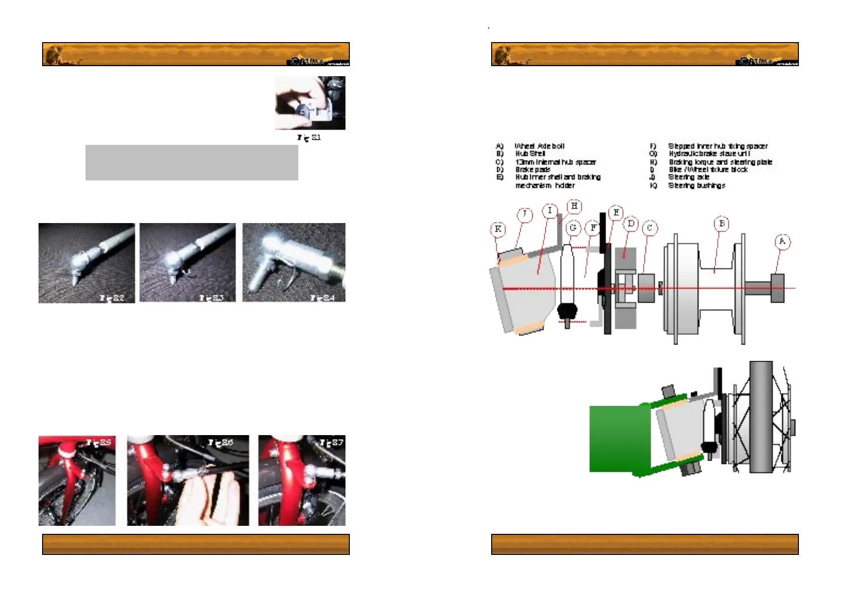
3. Rider Front wheel alignment and installation
9
All export models of the ‘Rider’ are delivered without the front wheels fully assembled. Please
follow these instructions carefully to ensure you install the wheels properly. Failure to do so
may result in hub damage, breaking malfunction and serious resultant injuries.
Assemble the wheel to the
frame, in the order depicted
in gure 9.1, with the braking
slave unit on the front side
of the hub as in g 9.2. The
brakes will have been aligned
before shipping so all you
need to do is mount the
wheel as shown in g 9.2 and
fasten the axle bolt tightly. If
the wheel bolt is not sufciently
tightened, the brakes will drag
and the wheel may work itself
loose.
While screwing the hubs in,
gently squeeze the brake levers a few times, to ensure that the hub shells are well centred.
If one or both of the brakes drag, you will need to adjust them. This should not be necessary
for the rst assembly. To see how to adjust the brakes, see section 4 on page 12, brake
adjustment & bleeding.
Fig
9.2,
rider
 Loading...