6
3 Service Navigation
3.1. Introduction
This service manual contains technical information, which allow service personnel’s to understand and service this model.
Please place orders using the parts list and not the drawing reference numbers.
If the circuit is changed or modified, the information will be followed by service manual to be controlled with original service manual.
3.2. Important Notice
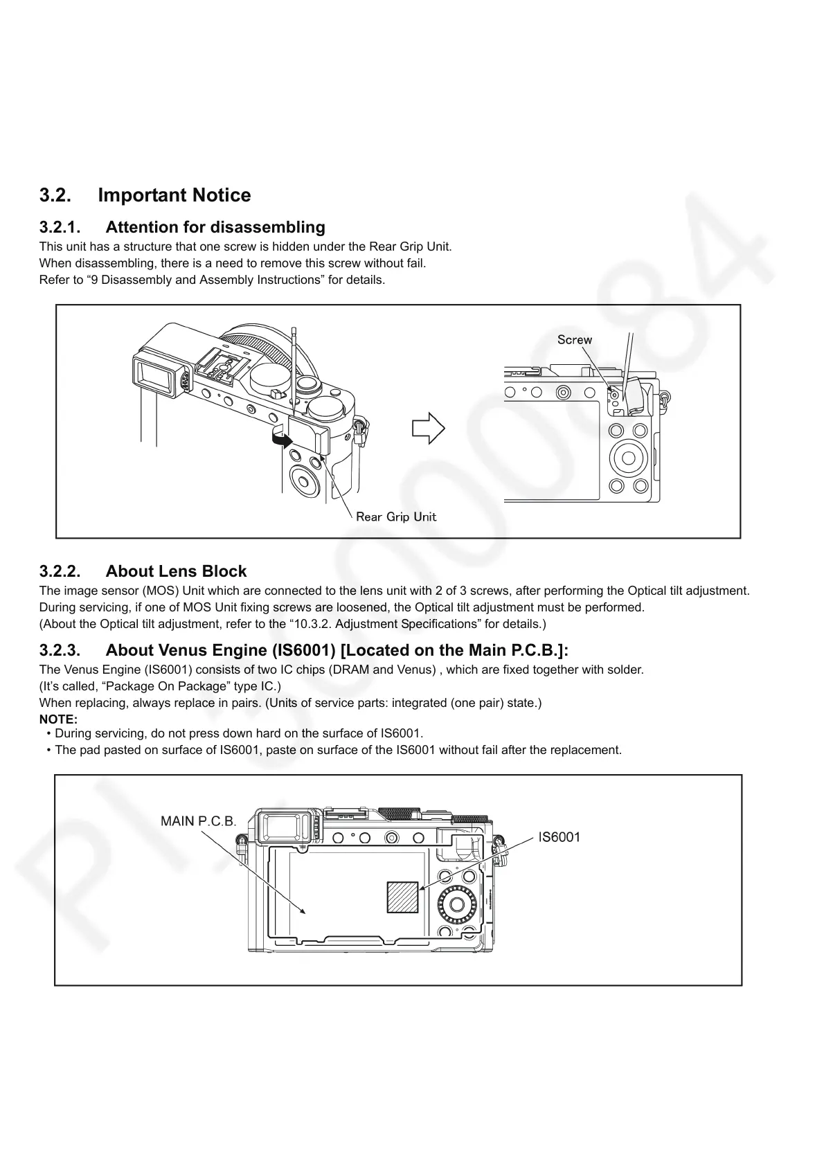
3.2.1. Attention for disassembling
This unit has a structure that one screw is hidden under the Rear Grip Unit.
When disassembling, there is a need to remove this screw without fail.
Refer to “9 Disassembly and Assembly Instructions” for details.
3.2.2. About Lens Block
The image sensor (MOS) Unit which are connected to the lens unit with 2 of 3 screws, after performing the Optical tilt adjustment.
During servicing, if one of MOS Unit fixing screws are loosened, the Optical tilt adjustment must be performed.
(About the Optical tilt adjustment, refer to the “10.3.2. Adjustment Specifications” for details.)
3.2.3. About Venus Engine (IS6001) [Located on the Main P.C.B.]:
The Venus Engine (IS6001) consists of two IC chips (DRAM and Venus) , which are fixed together with solder.
(It’s called, “Package On Package” type IC.)
When replacing, always replace in pairs. (Units of service parts: integrated (one pair) state.)
NOTE:
• During servicing, do not press down hard on the surface of IS6001.
• The pad pasted on surface of IS6001, paste on surface of the IS6001 without fail after the replacement.
3.2.4. About Flexible Cable and Connector
Do not touch carelessly so that the foreign body should not adhere to the terminal part of flexible cable and connector.
Wipe off with a clean cloth and the cotton bud, etc. when the terminal part is dirty.

 Loading...