21
INTELLIFLO
®
Variable Speed Pump Installation and User’s Guide
20
INTELLIFLO
®
Variable Speed Pump Installation and User’s Guide
Pump Reassembly
1. When installing the replacement shaft seal, use
silicone sealant on the metal portion before pressing
into the seal plate as shown.
Note: Use extreme care when applying sealant. Be
sure no sealant contacts the seal plate surface or
the ceramic seal. Allow sealant to cure overnight
before reassembling.
2. Before installing the rotating portion of the seal into
the impeller, be sure the impeller is clean. Use a
light density soap and water to lubricate the inside
of the seal. Press the seal into the impeller with
your thumbs and wipe off the ceramic and carbon
faces with a clean cloth.
3. Remount the seal plate to the motor.
4. Screw in the impeller lock screw (counterclockwise
to tighten).
5. Remount the diffuser onto the seal plate. Be sure the
plastic pins and holding screw inserts are aligned.
Note: Ensure that the seal plate o-ring is clean
and free of debris.
6. Grease the diffuser o-ring and seal plate gasket
prior to reassembly.
7. Assemble the motor subassembly to the pump
housing by using the two (2) through bolts for proper
alignment. Do not tighten the through bolts until all
six (6) bolts are in place and finger tightened.
Note: Ensure that the seal plate gasket is properly
seated inside of the pump assembly. The seal
gasket can be pinched between the seal plate and
the pump housing while tightening these six (6)
screws, preventing a proper seal and producing a
slow leak when the pump is restarted.
8. Reinstall the drive onto the top of the motor.
9. Fill the IntelliFlo
®
Variable Speed Pump with water.
Drive Assembly Removal and Installation
To remove the drive and control panel from the motor
assembly:
1. Be sure all electrical breakers and switches are
turned off before removing the control panel.
2. Disconnect the RS-485 communication cable
from the pump.
3. Remove the four (4) Phillips head screws from the
outer corners of the drive top cover.
4. Unplug the keypad top cover from the drive and set
it to the side in a safe place.
5. Remove the three (3) Phillips head screws, located
inside the drive, that anchor the drive to the motor.
6. Lift up the drive assembly and remove it from the
motor adapter located on top of the motor assembly.
Note: Be careful not to remove the gasket between
the drive and motor, it is critical in keeping moisture
out of the drive and motor. Replace the gasket if
damaged. Do not reassemble with a damaged or
missing gasket.
10. Reinstall the pump lid and plastic clamp. See
“Cleaning the Pump Strainer Basket” on page 18
for details
11. Reconnect the RS-485 communication cable to
the pump.
12. Prime the pump; refer to “Priming the Pump” on
page 5.
To avoid electrical hazard, never remove the four
torx-head screws from the intermediate drive
cover. There is a capacitor bank that holds an electrical charge even
when there is no power supplied to the pump.
To avoid dangerous or fatal electrical shock
hazard, switch OFF power to motor before working
on pump or motor.
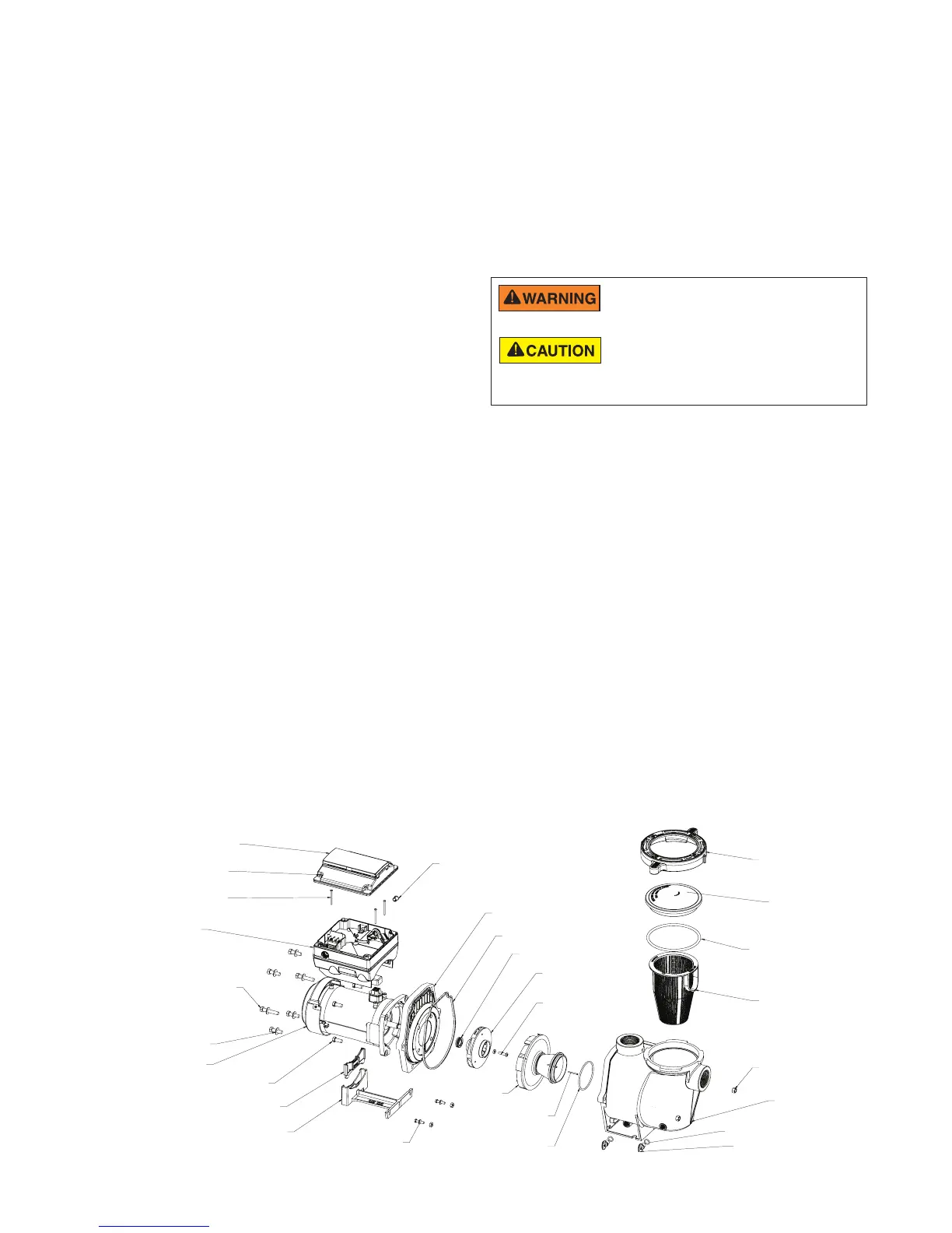
Pump Illustrated Parts View
FOOT
FOOT INSERT
MOTOR
WASHERS (6X)
SEAL PLATE TO
HOUSING BOLTS (6X)
DRIVE
DRIVE TO MOTOR
SCREWS (3X)
KEYPAD COVER
KEYPAD TO
DRIVE SCREWS
CAPTIVE (4X)
HEYCO PLUG FOR
KEYPAD RELOCATION CABLE
SEAL PLATE
SEAL PLATE GASKET
MECHANICAL SEAL
IMPELLER
IMPELLER SET SCREW
REVERSE THREAD
DIFFUSER
DIFFUSER SCREWS (2X)
DIFFUSER O-RING
LID
LOCKING RING
SEALPLATE TO
VOLUTE NUTS(2X)
DRAIN PLUGS (2X)
DRAIN PLUG O-RINGS (2X)
FOOT ATTACHMENT
HARDWARE
VOLUTE
BASKET
LID O-RING
MOTOR TO SEAL
PLATE BOLTS (4X)
 Loading...