3
INTELLIFLO
®
Variable Speed Pump Installation and User’s Guide
2
INTELLIFLO
®
Variable Speed Pump Installation and User’s Guide
INSTALLATION
Location
Note: Do not install this pump within an outer enclosure or
beneath the skirt of a hot tub or spa unless marked accordingly.
Note: Ensure that the pump is mechanically secured to the
equipment pad.
Be sure the pump location meets the following
requirements:
1. Install the pump as close to the pool or spa as possible.
To reduce friction loss and improve efficiency, use short,
direct suction piping returns.
2. Install a minimum of 5 feet (1.52 meters) from the inside
wall of the pool and spa. Canadian installations require a
minimum of 9.8 feet (3 meters) from pool water level.
3. Install the pump a minimum of 3 feet (.9 meters) from the
heater outlet.
4. Do not install the pump more than 10 feet (3.1 meters)
above the water level.
5. Install the pump in a well ventilated location protected
from excessive moisture (i.e., rain gutter downspouts,
sprinklers, etc.)
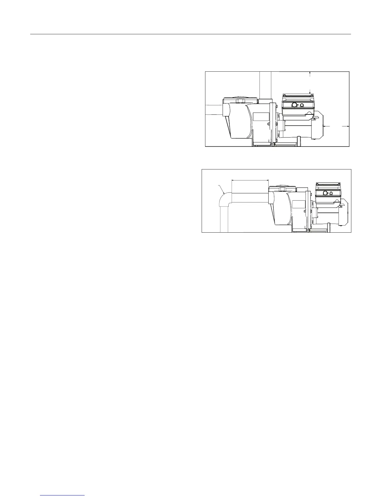
6. Install the pump with a rear clearance of at least 3 inches
(76.2 mm) so that the motor can be removed easily for
maintenance and repair. See Figure 1.
Piping
1. For improved pool plumbing, it is recommended to use a
larger pipe size. When installing the inlet and outlet fittings
(male adaptors), use thread sealant.
2. Piping on the suction side of the pump should be the same
or larger than the return line diameter.
3. Plumbing on the suction side of the pump should be as
short as possible.
4. For most installations Pentair recommends installing a valve
on both the pump suction and return lines so that the pump
can be isolated during routine maintenance. However, it is
recommended that a valve, elbow or tee installed in the
suction line should be no closer to the front of the pump than
five (5) times the suction line pipe diameter. See Figure 2.
Example:
A 2 inch pipe requires a 10 inch (254 mm) straight run in
front of the suction inlet of the pump). This will help the
pump prime faster and last longer.
Note: DO NOT install 90° elbows directly into the pump
inlet or outlet.
Electrical Requirements
• Install all equipment in accordance with the National Electrical
Code and all applicable local codes and ordinances.
• A means for disconnection must be incorporated in the fixed
wiring in accordance with the wiring rules.
Figure 2: Recommended Piping
Figure 1: Pump Rear and Overhead Clearance
Optional Keypad Relocation Kit
In special cases when the user lacks easy or
convenient access to the IntelliFlo
®
Variable Speed
Pump, a Keypad Relocation Kit (P/N 356904Z
[Almond] or P/N 356905Z [Black]) may be purchased
from your local pool equipment supplier. This kit allows
the user to remove the keypad cover from the top of
the drive and mount the keypad in a fixed location
with better access.
For installation instructions refer to the Keypad
Relocation Kit Installation Instructions provided with
the kit.
Fittings and Valves
1. Do not install 90° elbows directly into pump inlet.
2. Flooded suction systems should have gate
valves installed on suction and discharge pipes
for maintenance, however, the suction gate valve
should be no closer than five times the suction
pipe diameter as described in this section.
3. Use a check valve in the discharge line when
using this pump for any application where there is
significant height to the plumbing after the pump.
4. Be sure to install check valves when plumbing in
parallel with another pump. This helps prevent
reverse rotation of the impeller and motor.
Only a qualified plumbing professional should install the IntelliFlo
®
Variable Speed Pump. Refer to “Important Pump
Warning And Safety Instructions” on pages ii - iii for additional installation and safety information.
Note: The IntelliFlo pump cannot be connected in series with other pumps.
3 IN.
(7.6 CM)
MINIMUM
6 IN.
(15.2 CM)
MINIMUM
MIN 5 X SUCTION PIPE DIAMETER
ELBOW
 Loading...