Adjustment
11 - 24
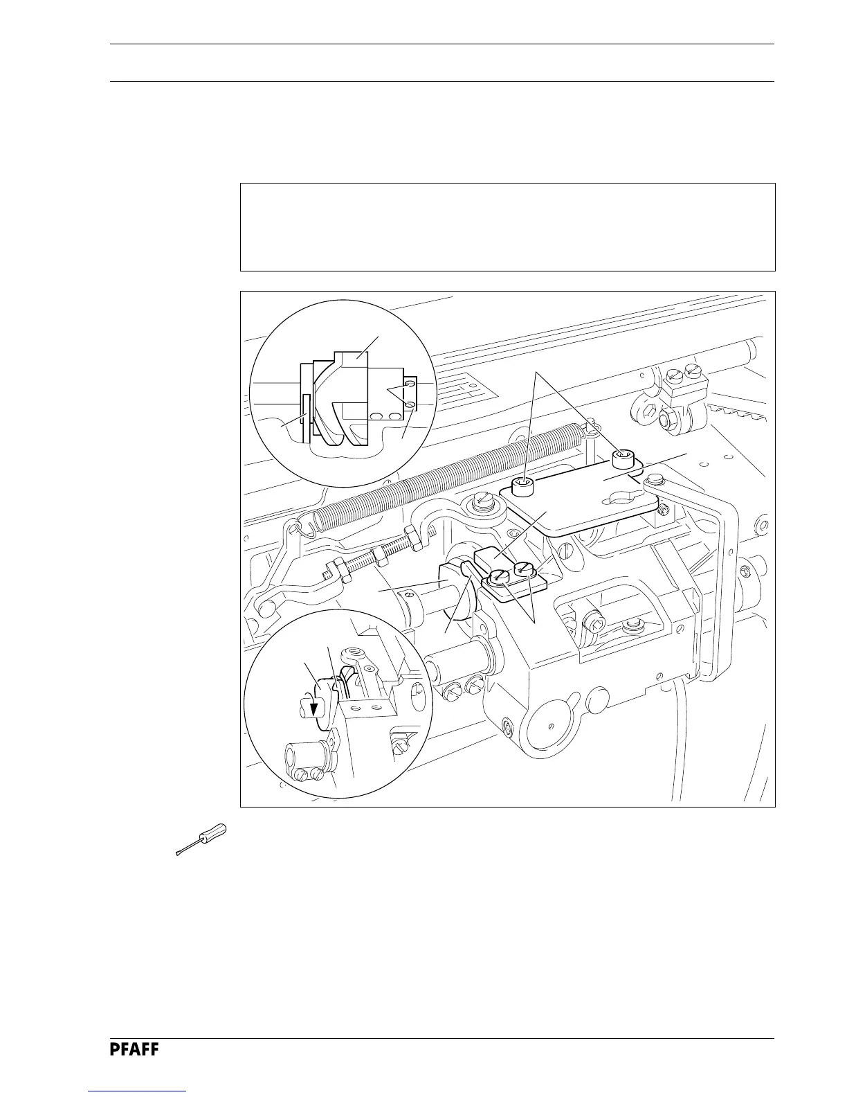
11.05 Adjusting the thread trimmer -900/56
11.05.01 Pre-adjusting the control cam
Requirement
1. The bearingsurface of control cam 5 must be laterally in the middle of pawl 8.
2. With the take-up lever at its TDC, the beginning of the largest eccentricity of the
bearing surface (in the direction of rotation) must be underneath the point of pawl 8.
8
5
● Remove catch 1 (screws 2).
● Remove plate 3 (screws 4).
● Loosen the four screws of control cam 5 and screws 6 of retaining collar 7.
● Move control cam 5 laterally in accordance with requirement 1.
● In this position bring retaining collar 7 to rest on control cam 5 and tighten screws 6.
● Bring the take-up lever to its TDC by turning the balance wheel.
● Turn control cam 5 in the direction of rotation in accordance with requirement 2, taking
care to note that it is touching retaining collar 7.
● In this position, tighten the four screws on control cam 5.
5
Fig. 11 - 22
6
7
3
4
1
2
5
8
8
 Loading...