Removing the piston
- Install piston and wrist pin onto the connecting
rod, aligning the piston arrow the arrow facing to-
wards the exhaust.
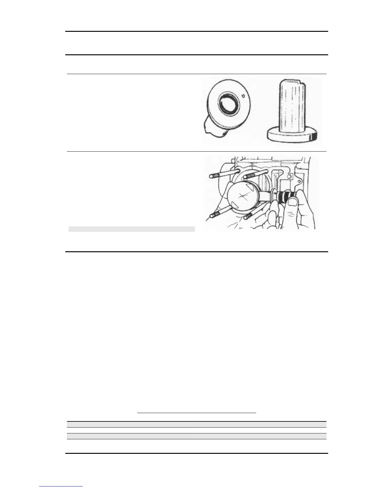
- Fit the pin stop ring onto the appropriate tool.
Specific tooling
020448Y Pin lock fitting tool
- With the opening in the position indicated on the
tool, set the lock ring into position in the tool with
the punch.
- Rest the tool on the piston paying attention that
the 90°chamfered side faces upwards as indicated
in the figure.
- Fit the gudgeon pin stop using the plug.
CAUTION
USING A HAMMER TO POSITION THE RINGS CAN DAM-
AGE THE LOCKING HOUSING.
Choosing the gasket
- Provisionally fit the piston into the cylinder, without any base gasket.
- Fit a dial gauge on the specific tool, then rest both on a stop surface.
- Zero set the dial gauge on the stop surface. Keeping the zero position, assemble the tool on the cylinder
and lock it with 2 nuts as shown in the figure.
- Rotate the crankshaft until TDC (the inverted point of the dial gauge rotation)
- Measure piston protrusion compared with the head plane and determine the gasket thickness to be
used according to the table below. By correctly identifying the cylinder base gasket thickness, an ade-
quate compression ratio is maintained.
- Remove the specific tool and the cylinder.
Characteristic
Standard compression ratio
C.R. 11.5 ÷ 12 ÷ 1
CYLINDER BASE GASKET THICKNESS
Specification
Desc./Quantity
Cylinder height 56.45 ± 0.05
Head gasket thickness (fibre) 0.95 ± 0.06
Measure detected 0.9 ± 0.05
Base gasket thickness 0.4
MSS ZIP 100 4T Engine
ENG - 93
 Loading...