Do you have a question about the Pioneer DEH-80PRS Series and is the answer not in the manual?
| Channels | 4 |
|---|---|
| Preamp Outputs | 6-channel |
| Preamp Voltage | 5 volts |
| Subwoofer Output | Yes |
| Bluetooth | No |
| Auxiliary Input | Front |
| CD Playback | Yes |
| DIN Size | Single DIN |
| CEA-2006 Compliant | Yes |
| Display Type | LCD |
| MP3 Playback | Yes |
| WMA Playback | Yes |
| AAC Playback | Yes |
| FLAC Playback | Yes |
| HD Radio | No |
| Remote Control | Yes |
| Built-in DSP | Yes |
| Built-in Parametric EQ | Yes |
| Time Alignment | Yes |
| MOSFET Power Supply | Yes |
| High-Voltage Preamp Output | Yes |
| Digital Time Correction | Yes |
| Auto EQ | Yes |
| Advanced Sound Retriever | Yes |
| Dual Zone | No |
| iPod/iPhone Control | Yes |
| Detachable Faceplate | Yes |
| Power Output | 50 Watts x 4 Channels |
| RMS Power Output | 14 Watts x 4 Channels |
| Peak Power Output | 50 watts |
| USB Input | Front |
| Display | LCD |
| SIRIUS or XM Radio Ready | Yes |
| Equalizer | 16-Band Graphic Equalizer |
Covers general warnings, health, and environmental precautions.
Details specific safety measures related to laser diodes.
Outlines service handling, soldering tips, and component precautions.
Details general, audio, and network specifications.
Covers CD, USB, SD, Tuner, and Bluetooth specifications.
Covers check points, PCB locations, jigs list, and cleaning procedures.
Presents the overall block diagram of the system.
Guides through operational flow and lists error codes for diagnosis.
Addresses error messages for external storage and applications.
Explains how to enter and use display and CD test modes for service.
Details steps for removing the panel, mecha unit, and pickup unit.
Covers CD adjustment cautions, test modes, and waveform analysis.
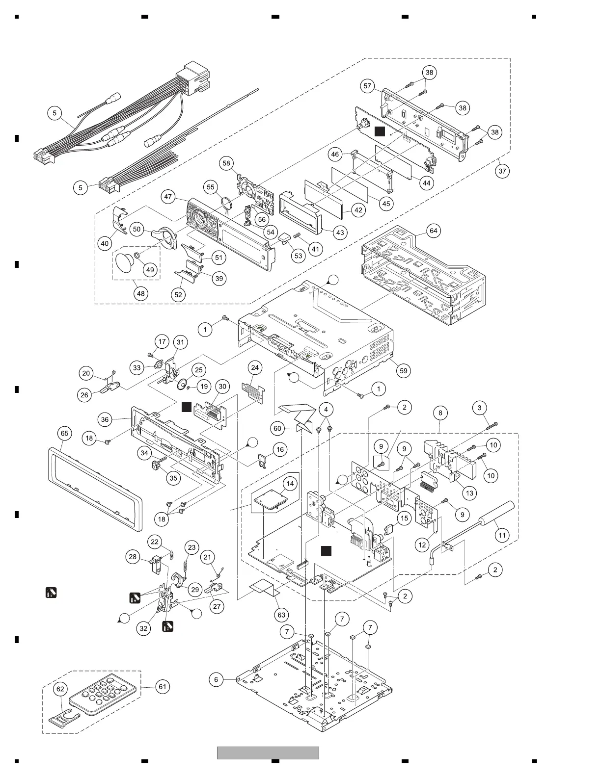
Provides exploded views for packing and exterior components.
Lists parts for the CD mechanism module and the electrical components.
Details schematics for the Tuner Amp unit's system, media, DSP, and power supply blocks.
Provides schematics for Keyboard, CD Core, Panel units, and waveforms.
Shows the PCB connection diagram for the Tuner Amp Unit.
Illustrates PCB connection diagrams for Keyboard, CD Core, and Panel units.
Lists electrical components including ICs, transistors, and resistors/capacitors.