6. SERVICE MODE
7. DISASSEMBLY
1
1
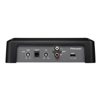
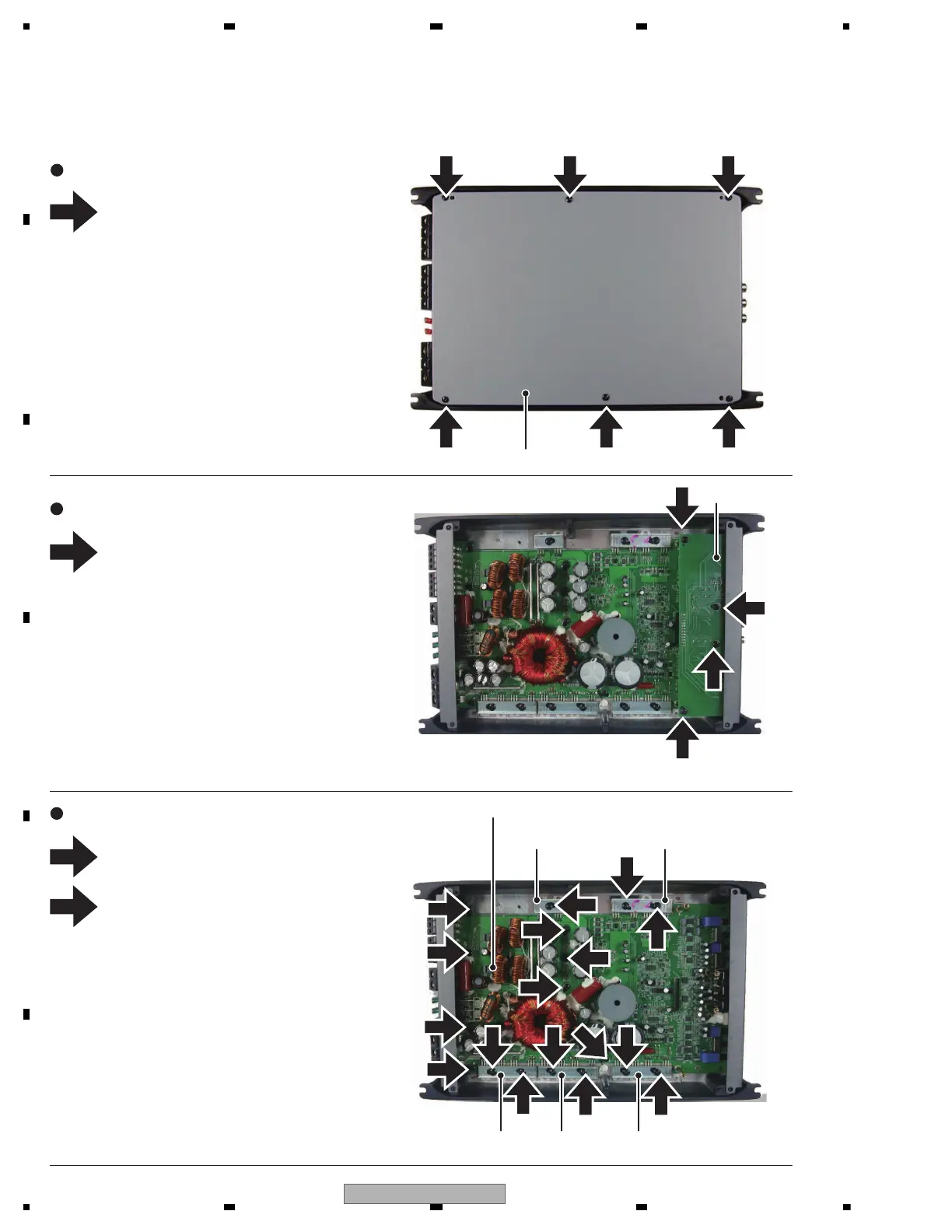
- Removing the SUB PCBA (Fig.2)
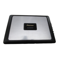
- Removing the Case (Fig.1)
Fig.3
Fig.2
Fig.1
Remove the six screws and then
remove the Case.
Remove the four screws and then
remove the SUB PCBA.
2
1
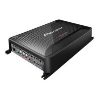
- Removing the MAIN PCBA (Fig.3)
Remove the nine screws and then
remove the five Holders.
Remove the eight screws and then
remove the MAIN PCBA.
11
1
1
1
1
1 1
1
Case
SUB PCBA
Holder Holder
PCB Kit
1
1
1
1 1
1
2
2
2
1
1
2
2
1
2
2
2
HolderHolder
Holder
Apply the glue (TB1401B or TB1401M) to
all screws when you assemble the product.
When you replace parts that are applied
silicon glue, re-apply silicon glue to the
same place after replacing.
1
 Loading...