EasyManuals Logo

Pioneer GM-D9605 Service Manual

Pioneer GM-D9605
29 pages
To Next Page IconTo Next Page
To Previous Page IconTo Previous Page
Page #16 background imageLoading...
Page #16 background image
GM-D9605/XEEL
16
1234
1234
C
D
F
A
B
E
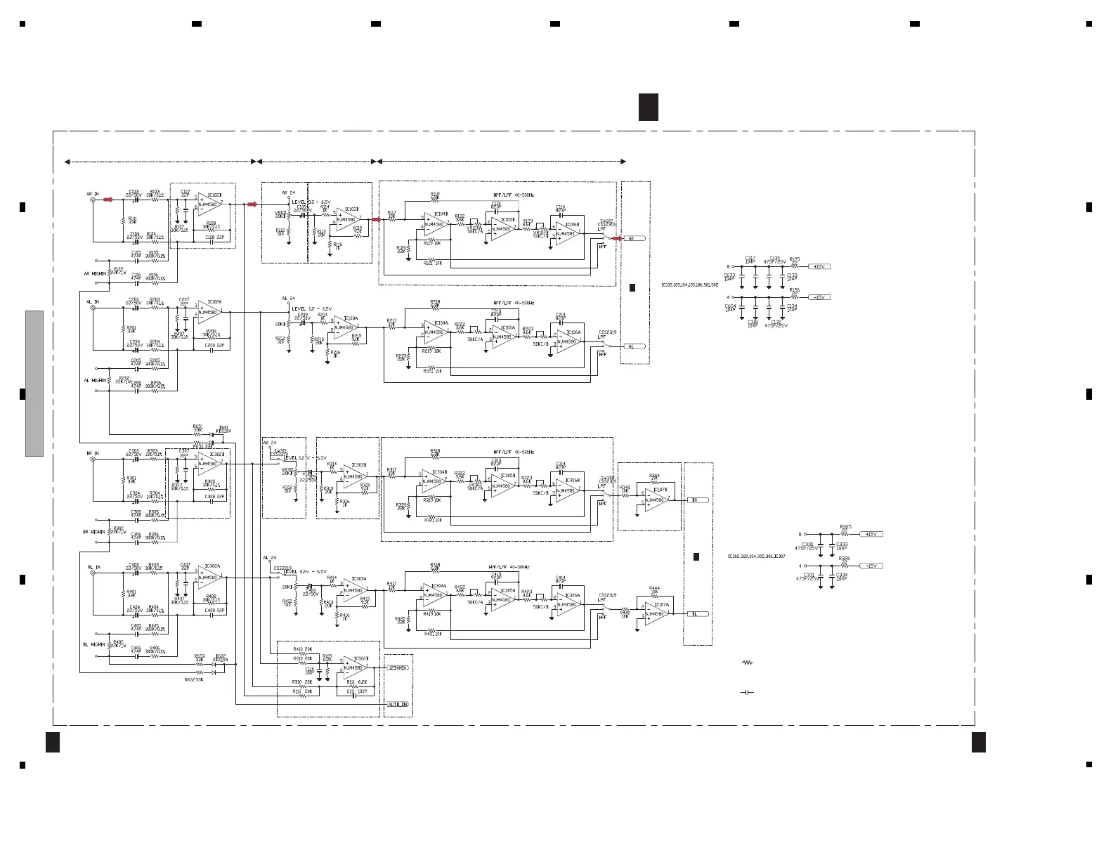
10. SCHEMATIC DIAGRAM
10.1 MAIN PCBA (AL/AR and BL/BR ch PART)
A
1/4
A
1/4
MAIN PCBA(AL/AR and BL/BR ch PART)
1/4
A
2/4
A
2/4
A
ISOLATOR
LPF/HPF/PASS
GAIN : 0.0dB
(Vo=-19.0dBv)
GAIN : -11.0[6.5V]/12.0dB[Normal]/20.0dB[0.2V]
(Vo=-19.0dBv)[Normal]
GAIN : 0dB
(Vo=-31.0dBv)(Vi=-31.0dBv)
GAIN CONTROL
INVERTOR
BUFFER
GAIN : 20dB
ISOLATOR
LPF/HPF/PASSGAIN CONTROL BUFFER
Ach/Bch MIXING
GAIN : 1.0dB
Symbol indicates a resistor.
No differentiation is made between chip resistors and
discrete resistors.
NOTE :
Symbol indicates a capacitor.
No differentiation is made between chip capacitors and
discrete capacitors.NM : No Mount
Note: When ordering service parts, be sure to refer to " EXPLODED VIEWS AND PARTS LIST" or
"ELECTRICAL PARTS LIST".
SCHEMATIC DIAGRAM

Other manuals for Pioneer GM-D9605

Questions and Answers:

Question and Answer IconNeed help?

Do you have a question about the Pioneer GM-D9605 and is the answer not in the manual?

Pioneer GM-D9605 Specifications

General IconGeneral
Bass boost0 - 18 dB
Amplifier classF/D
High pass filterYes
RMS output power (max)2000 W
Signal-to-Noise Ratio (SNR)94 dB
Number of amplifier channels5 channels
RMS power output per channel (2 Ohm)100 W
RMS power output per channel (4 Ohm)75 W
Maximum power output per channel (4 Ohm)150 W
Audio RCA inputs6
Product colorBlack
Weight and Dimensions IconWeight and Dimensions
Depth200 mm
Width315 mm
Height51 mm

Related product manuals