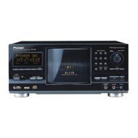
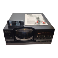
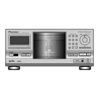
PD-F1007
44
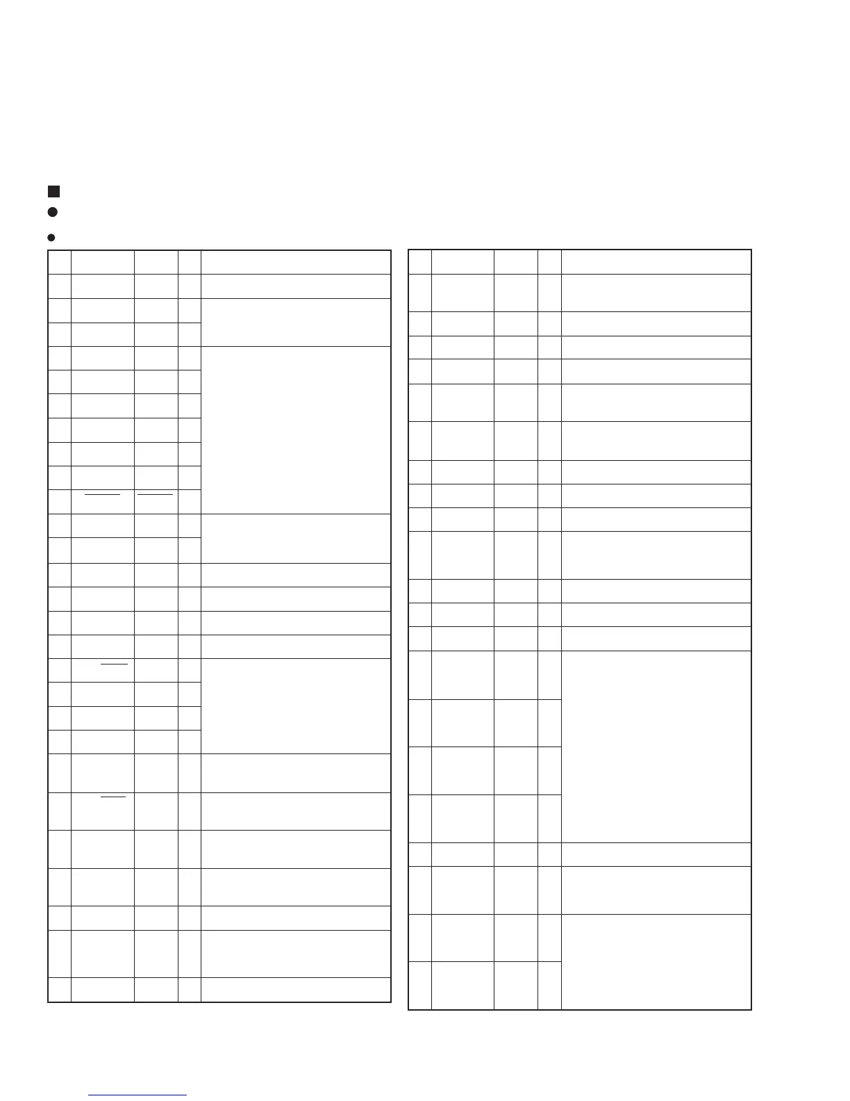
No. Symbol Name I/O Description
32 P11/ANI1 KBDAT I Keyboard communication data
transmission and reception
33 P10/ANI0
Not used
O Open
34 AVDD AVDD – +5V
35 AVREF
AVREF
– GND
36 P03/INTP3 DCS I Serial communication timing input
from the main microcomputer
37 P02/INTP2 KBCLK I Keyboard communication data clock
input
38 P01/INTP0 JOG1 I JOG input 1
39
P00/INTP0/TI0
RMDT I Remote control data input
40 VSS VSS – GND
41 P74
||
Not used
O OPEN
44 P71
45 P70 JOG2 I JOG input 2
46 VDD VDD – +5V
47 P127/FIP52 STBL O STANDBY–LED
48 P126/FIP51 S36
|| |O
54 P120/FIP45 S30
55 P117/FIP44 S29
|| |O
62 P110/FIP37 S22
Segment output for FL drive
63 P107/FIP36
S21
|| |O
70 P100/FIP29 S14
71 P97/FIP28 S13
|| |O
78 P90/FIP21 S6
79 VLOAD VLOAD – –30V
80 P87/FIP20 S5
| | | O Segment output for FL drive
84 P84/FIP16 S1
85 P83/FIP15 G16
|| |O
87 P80/FIP13 G14
DIGIToutput for FL drive
88 FIP12 G13
|| |O
100 FIP0 G1
No. Symbol Name I/O Description
1 VDD VDD – +5V
2 P37
Not used
O
Open
3 P36/BUZ
Not used
O
4 P35/PCL KD5 I
5 P34/TI2 KD4 I
6 P33/TI1 KD3 I
Key data input
7 P32/TO2 KD2 I
8 P31/TO1 KD1 I
9 P30TO0 KD0 I
10 RESET RESET I CPU reset (L: Reset)
11 X2 X2 – Connected to System clock oscillator
(4.19 MHz)
12 X1 X1 –
13 IC IC – GND
14 XT2 XT2 – Not Connect (open)
15 P04/XT1
Not used
O Only for input: Input of GND
16 VDD VDD – +5V
17 P27/SCK0
Not used
O
18
P26/SO0/SB1
Not used
O
Open
19
P25/SI0/SB0 Not used
O
20 P25/BUSY
Not used
O
21 P23/STB DREQ O Completion of transmission setting
to the main microcomputer
22 P22/SCK1 DCLK I Clock input for serial communication
with the main microcomputer
23 P21/SO1 KYDT O Serial data output to the main micro-
computer
24 P20/SI1 DPDT I Serial data input from the main micro-
computer
25 AVSS AVSS – GND
26 P17/ANI7
||
Not used
O OPEN
30 P13/ANI3
31 P12/ANI2 ACRY O Main microcomputer power ON/OFF
7. GENERAL INFORMATION
7.1 PARTS
7.1.1 IC
¶ The information shown in the list is basic information and may not
correspond exactly to that shown in the schematic diagrams.
PD4997A (IC701: DISPLAY BOARD ASSY)
Display Control Micro-computer
Pin Function
 Loading...