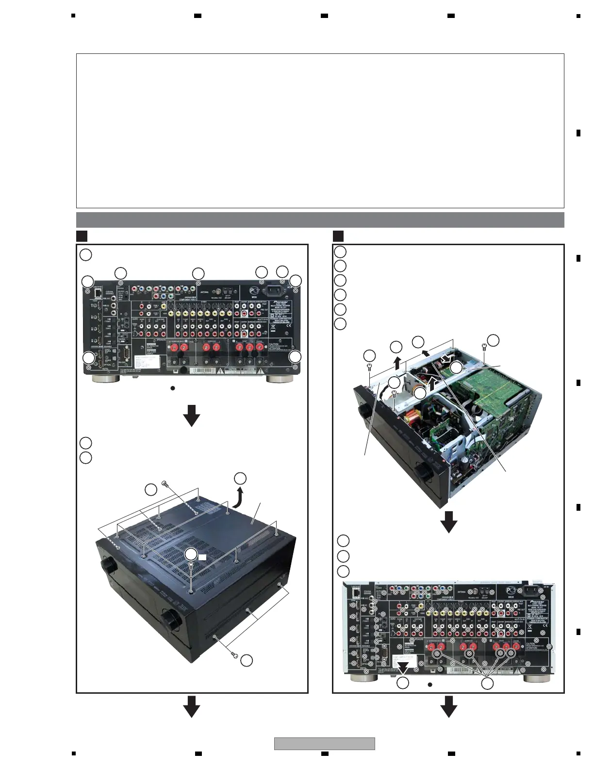
7. DISASSEMBLY
Note 1: Even if the unit shown in the photos and illustrations in this manual may differ from your product, the procedures
described here are common.
Note 2: For performing the diagnosis shown below, the following jigs for service is required:
• 27P FFC (GGD1588)
• 19P FFC (GGD1589) x2
• 21P FFC (GGD1590)
• 16P FFC (GGD1591)
• 30P+13P board to board extension jig cable (GGD1592)
• 17P+19P board to board extension jig cable (GGD1593)
• 5P PH HOUSING ASSY (GGD1594) x3
Note 3: Before starting the diagnosis, wait for three minutes until the electricity of the unit is
discharged.
1
Remove the eight screws.
2
Remove the fourteen screws.
3
Remove the Bonnet.
Bonnet
1
1. Disassembly
1
1
1
1
1
1
1
1
Rear view
Rear view
Rear Panel
2
Bonnet
Left Beam 81
Center Beam V1
PCB Holder
3
2
2
×8
2
×3
×3
1
3
1
2
6
Remove the Rear Panel.
8
Remove the four Cushion circle 14B.
9
9
Remove the 71 screws.
4
7
7
Remove the two screws.
2
1
Remove the Center Beam V1.
3
Remove the three screws.
4
Disconnect the one connector.
5
5
6
Remove the PCB Holder from the Left Beam 81.
Remove the Left Beam 81.
 Loading...