SPECIFICATIONS
Operatin
Volta
e Ran
e: 8.5V - 14.4V
Maximum Voltage: 16.0V (non-operating)
Over-voltage shut-off 15.5V
Motor Current Limit: 100 Amps (+10%, -5%)
Output Time Rating (@100 Amps): 1.5Min. Minimum (ambient & initial temp<25ºC)
Continuous Current (Ambient<25ºC) 65 Amps (75 Amps in Le-Series Unit)
Maximum Run without stop: 25 to 30 Seconds
sofware limited
Input control current, Max.(@ 13V) 0.3 mA
Standb
Current
12.6V
< 18m
Buzzer or LED output: 5 Volts, maximum 15mA
Standb
Time
25% char
e remains
40 da
s
start with 20 AH batter
, full
char
ed
Operating Temperature Range: -25ºC to 50ºC
Storage Temperature Range: -40ºC to 85ºC
Environmental: Solid State Controller Unit is100% RoHS compliant.
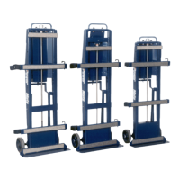
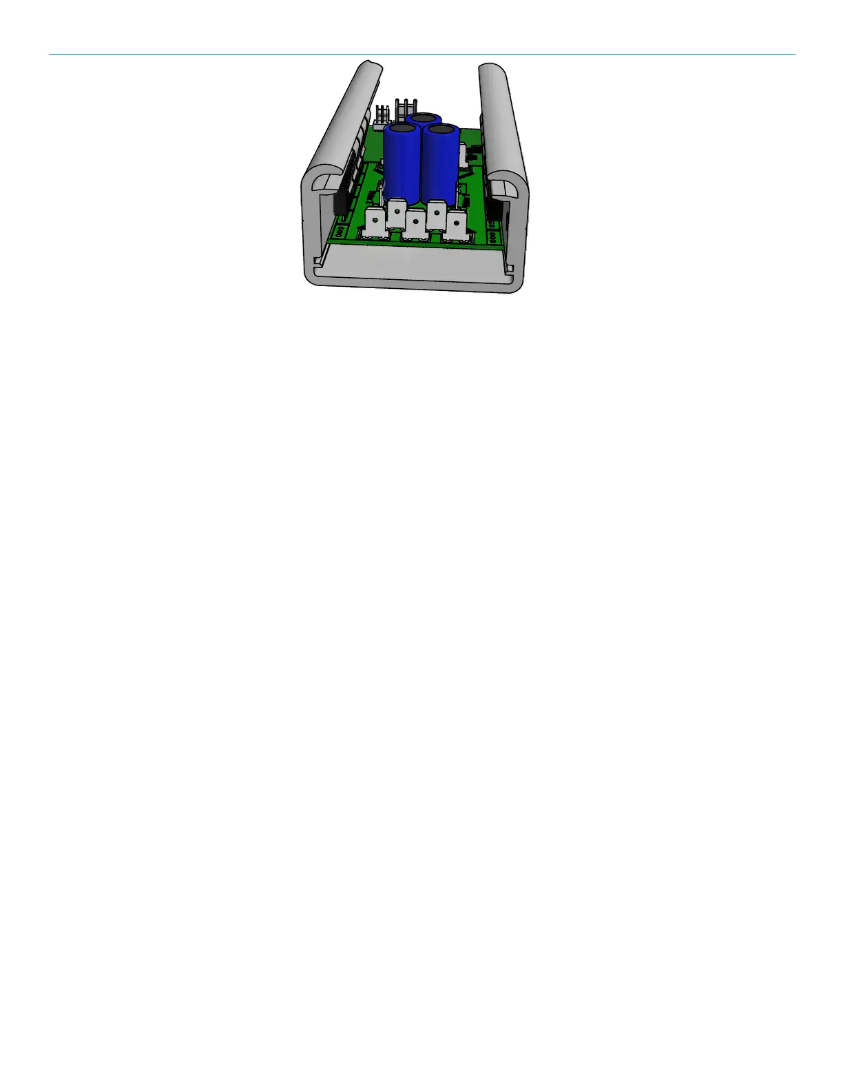
STAIR CLIMBER SOLIDSTATE CONTROLLER
The Stair Climber Solid State Controller is a fully solid state Pulse Width Modulated (PWM) controller. Its
advanced microprocessor based control implements a state-of the-art power MOSFET motor drive. Advanced
features provide improved functionality, smoother operation, reduced mechanical stress, and protects against
abuse and system faults.
ADVANTAGES
- Reduced peak current reduces power loss in batteries, motor, and cabling.
- Reduced peak current reduces battery stress, increased service life.
- Reduced peak torque reduces mechanical stress, increasing service life of the gear train and motor.
- Smooth operation "feel" by controlled acceleration and deceleration (motor voltage ramp-up and
ramp-down) eliminating jerkiness.
- Automatically slows speed with heavy loads, improving control and safety.
- Overload protection shuts off if lift load is too heavy.
- Protects batteries by limiting minimum loaded voltage to 8.5 volts.
- Internal protections for many types of internal and external faults.
- Protects controller by inhibiting operation if battery voltage is to high.
- Detects battery+ or battery- short to frame and inhibits motor operation.
- Limits continuous operation to <30 seconds. Control wiring fault protection.
- Alerts to low or excess control heating (from over-use).
- Alerts to overload or excess continuous run time (control fault).
- Alerts to battery+ or battery- short to frame.
- Alerts to internal controller faults.
- Low standby power of less than 20mA.
FAULT ALERTS
Faults are indicated by a buzzer producing a series of beeps to indictate various faults as follows:
One Beep - Overload condition (too much weight on Unit) - Reduce Load
- Maximum run time (25-30sec.) exceeded - Release and re-apply switch
Two Beeps - Low Battery - Recharge Battery
Three Beeps- Battery+ or Battery- shorted to frame. HALT USE AND RETURN FOR REPAIR
-System Fault - FAULTY UNIT -HALT USE AND RETURN FOR REPAIR
Four Beeps - Overheating due to excessive use (many minutes) - Allow five minutes to cool
PowerMate
Operation Manua
PN 010710 Rev.E
Component 052810
Eng. 05/ 08/ 14
6.02
 Loading...