INSTRUCTIONS PW150/PW200
4
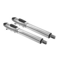
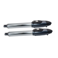
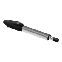
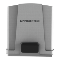
2.3.1 PW150/PW200 Electromechanical Gear Motors
PW150/PW200 consists of a worm screw reduction
gear and a 24V direct current motor. The gear motor
could be released manually by special release keys
when there is a power failure.
The gear motor is installed with two post brackets, one
rear plate and one front plate for the installation.
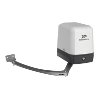
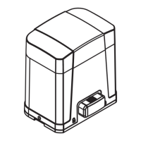
2.3.2 Control Box
Front bracket 1pce 1pce
Rear bracket 1pce 1pce
M8*40L hex bolt 1pce 1pce
M8 self-locking nut 1pce 1pce
M12 *8L hex bolt 1pce 1pce
M12 Steel bar 1pce 1pce
Release key 2pcs 2pcs
Table 1: List of small parts PW150 PW200
5*30 Screw 4 pcs
Nylon screw anchor 4 pcs
Table 2: List of small parts for Control Box Quantity
Figure 3
Figure 4
Figure 5
Figure 6
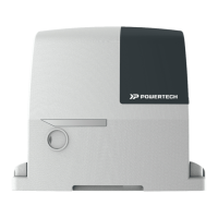
2.3.3 PH-1 Photocells
The pair of PH-1 photocells has to be installed on the
wall and connected to the control panel. The function of
the photocells is to detect the obstacles found on the
optical axis between the transmitter (TX) and the
receiver (RX).
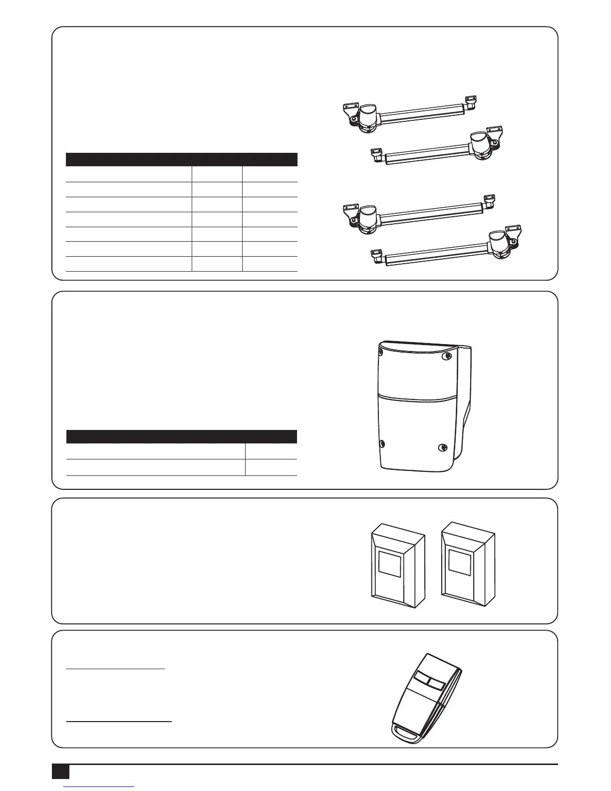
2.3.4 PR-1 Radio Transmitter
In dual gate installation:
Press the button “A” on the transmitter for dual-gate operation.
Press the buttom “B” on the transmitter for single-gate operation.
In single gate installation:
Press the buttom “A” on the transmitter for single-gate operation.
TX RX
PW150
PW200
Control box consists of one control panel with
incorporated receiver, one transformer and two back-up
batteries.
Control box provides the complete automation of the gear
motors and other accessories of PW150/PW200 kit.
To connect separate terminals on the control panel and
activate the gear motors and other accessories, the
installation manual has to be carefully read beforehand.
A
B
 Loading...