EasyManuals Logo
Home>PROLiNK>UPS>Professional II+ Series

PROLiNK Professional II+ Series User Manual

PROLiNK Professional II+ Series
24 pages
To Next Page IconTo Next Page
To Previous Page IconTo Previous Page
Page #6 background imageLoading...
Page #6 background image
4
2-2. Back Panel Display
INSPIRE 906-ES / INSPIRE 910-ES
Diagram 1: 6K/10K Back Panel
Diagram 2: Terminal Input/Output Tower
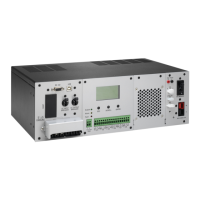
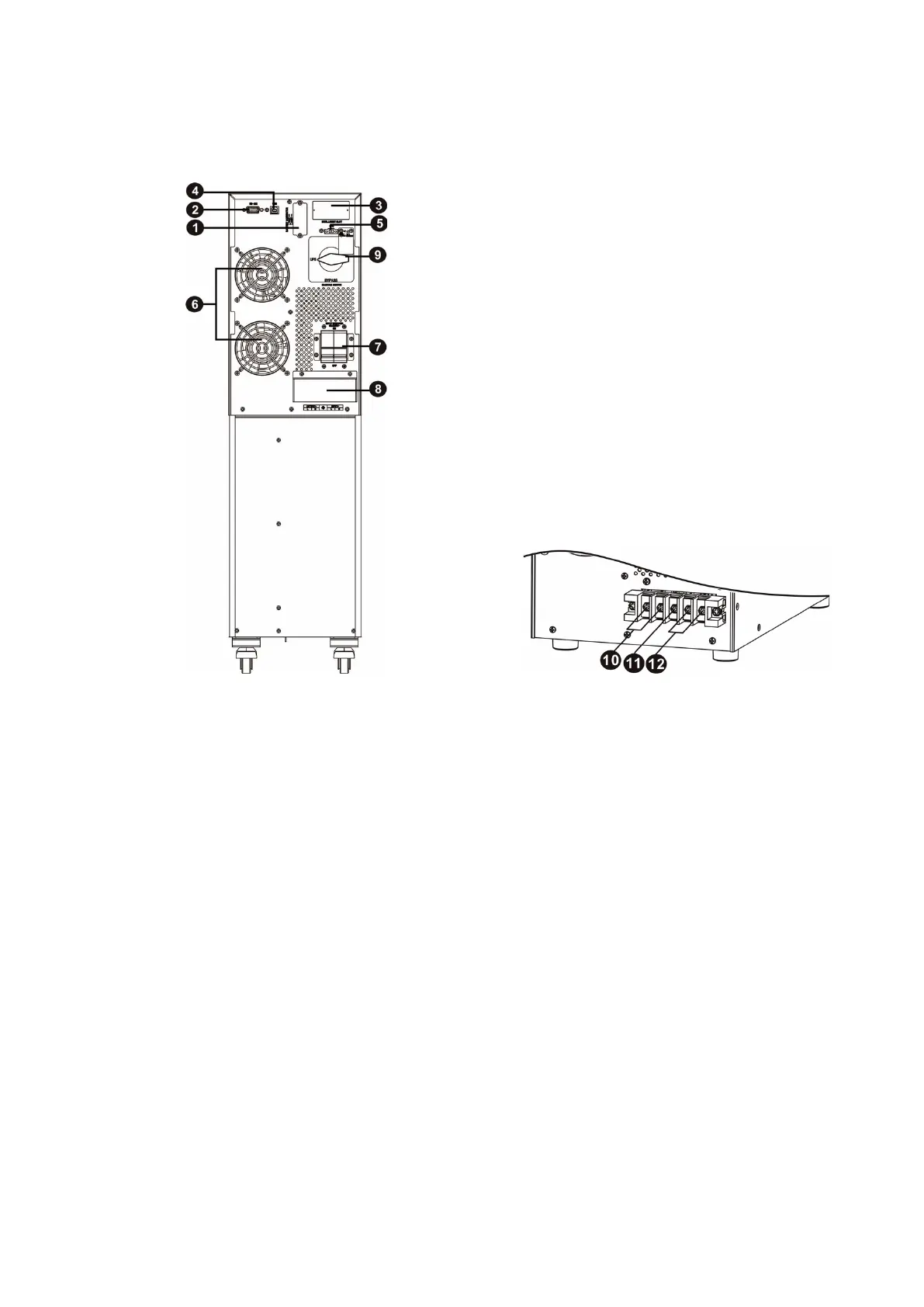
1. Additional battery connectors
2. RS-232 communication port
3. Intelligent slots
4. USB communication port
5. Connector intended as Emergency power off
function (EPO connector)
6. Cooling fan
7. Line input circuit breaker (Pemutus sirkuit
saluran Input)
8. Input/Output Terminal (See Diagram 2 and
for details)
9. Maintenance with bypass switch (optional)
10. Terminal Output
11. Terminal Grounding
12. Terminal Utility input
13. Battery input circuit breaker

Questions and Answers:

Question and Answer IconNeed help?

Do you have a question about the PROLiNK Professional II+ Series and is the answer not in the manual?

PROLiNK Professional II+ Series Specifications

General IconGeneral
BrandPROLiNK
ModelProfessional II+ Series
CategoryUPS
LanguageEnglish

Related product manuals