12
ENFORCER V11 INSTALLATION GUIDE
CONNECTING PERIPHERALS
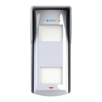
Wiring an external siren
PGM STB BELL Z33 COM +12V Z34D1- D2+ D3 D4
SCB
SAB
J3
B (G2)
A (G3)
J4
J7
LED
DISABLE
EXT
INT
J8
SOUNDER
J12
BL
TAMPER
SOUNDER
Red
Gold
Red
Red
To create the siren tamper circuit, a 2k2 resistor is required across 0V supply and one of the tamper terminals in
the external siren. The other tamper terminal should be connected to the tamper return (either zone 33 or 34 on
the I/O board). Note, the zone must be programmed as ‘tamper’.
The resistor value will correspond to the value selected in ‘
WiRing ChoiCe’.
IMPORTANT NOTE: The external siren connected needs to be set in SCB mode unless it is a Pyronix
external siren.
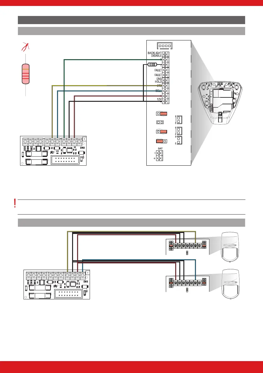
Wiring zones
PGM STB BELL Z33 COM +12V Z34D1- D2+ D3 D4
+ -
6K8
5K6
4K7
2K2
1K
5K6
4K7
2K2
1K
TAMPERALARM
ALARM
NCNO
TAMPER LED
+ -
6K8
5K6
4K7
2K2
1K
5K6
4K7
2K2
1K
TAMPERALARM
ALARM
NCNO
TAMPER LED
The End of Line (EOL) value for all wired zones is programmed in ‘Choose Mode’. At default the resistor values are
4k7 for alarm and 2k2 for tamper.

 Loading...