10W HF Linear PA kit assembly 1.00 10
3.4 Wind and install inductor L201
Start with the inductors and transformers because they are difficult to install when the other
components are all around them.
The BN43-202 core is the one NOT in the small plastic zip-lock bag. First use a drill bit twisted
by hand, to gently remove any rough edges to the holes, that could cut into the wire.
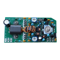
L201 is a simple inductor made of 4 turns of the 0.4mm (Medium thickness) wire wound around
the BN43-2402 binocular core. “One turn” means the wire goes through both holes. The start and
end wires of the toroid wire therefore are both on the same side.
Install it on the PCB, cut the wires to 2mm and as usual, solder it for at least 10 seconds to ensure
the enamel burns off.
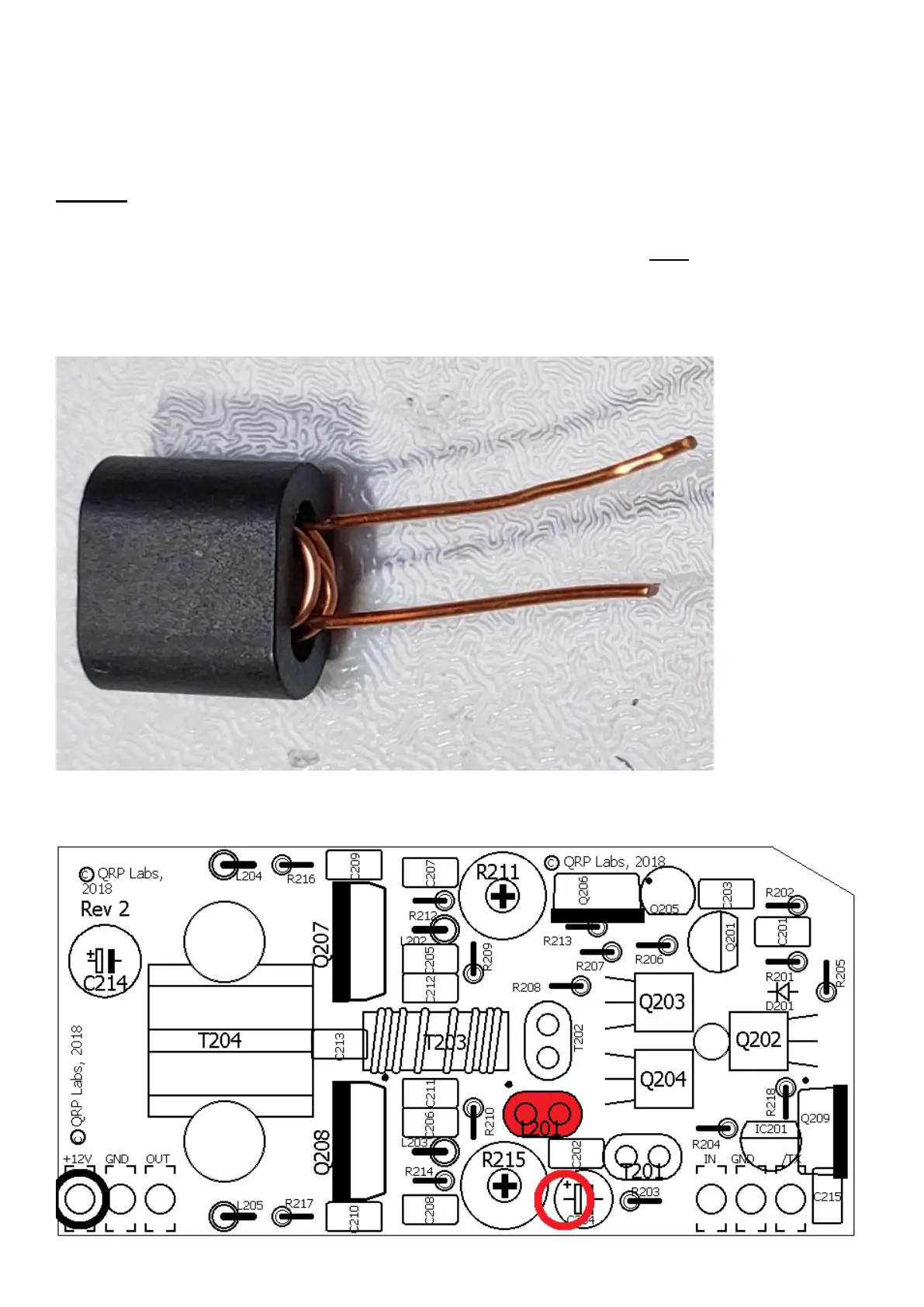
Test for DC continuity between the 12V pad of the PCB (indicated in the black circle) and the
positive pad of capacitor C204 (indicated in the red circle).
 Loading...