10W HF Linear PA kit assembly 1.00 26
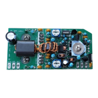
3.26 Install transistors Q202, Q203 and Q204
These are BS170 MOSFETs. The transistors should be installed in the positions
shown, with their flat faces all facing the hole in the center of the three BS170s.
Do not solder them yet. Bend over the transistors so that they lay flat on the
PCB, in the rectangular outlines shown on the PCB silkscreen. When the
transistors are lying with their flat faces flush against the PCB, and they are not obscuring the hole
drilled in the PCB in their center, you can solder them in position.
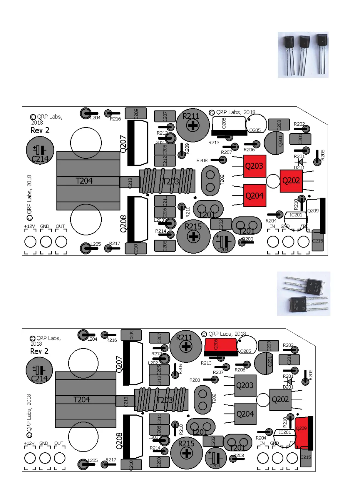
3.27 Install transistors Q206 and Q209
These are IRFU9024 P-channel MOSFETs. The transistors must be installed
correctly, with the exposed metal pad on the bottom of the transistor aligned
with the solid black line of the PCB silkscreen. Inspect the joints with a jeweller’s
loupe or magnifying glass to be sure the connections have been made.
 Loading...