10W HF Linear PA kit assembly 1.00 25
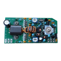
3.24 Install diode D201
Diode D201 is the 1N4004 and the direction of installation is critical. The white stripe on the diode
body must be aligned with the left-side (bar) of the diode arrow symbol on the PCB. The diode is
installed vertically. Bend the wire end in a U-shape, at the end of the diode body OPPOSITE the
white stripe. Then install the white stripe end next to the PCB in the left of the two holes, and bent-
over-wire-end (non-white stripe end) in the right of the two holes. This makes sure the bent-over
wire is not next to the washer of the BS170 installation; therefore, no short-circuit will occur.
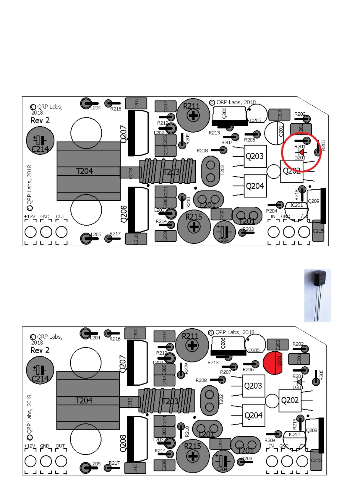
3.25 Install transistor Q201
Q201 is a 2N3904 transistor. It looks similar to all the BS170 transistors so check the
writing on the component carefully. Bend the middle leg slightly away from the flat face
so that it fits the triangular holes on the PCB. Ensure the transistor flat is orientated the
same way as the silkscreen flat.
 Loading...