10W HF Linear PA kit assembly 1.00 28
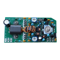
3.30 Install transistors Q207 and Q208
These transistors are the power amplifier transistors, IRF510
MOSFETs.
These transistors must be installed on the BOTTOM of the board so
that they can be bolted directly to the heatsink.
The leads of the IRF510 must be bent upwards through 90-degrees immediately at their exit-point
from the IRF510 body. You only get ONE chance at this – if you bend them the wrong way
and you try to bend them back to correct it, the wires will snap off. The following three
photographs all show the IRF510 with the leads bent correctly.
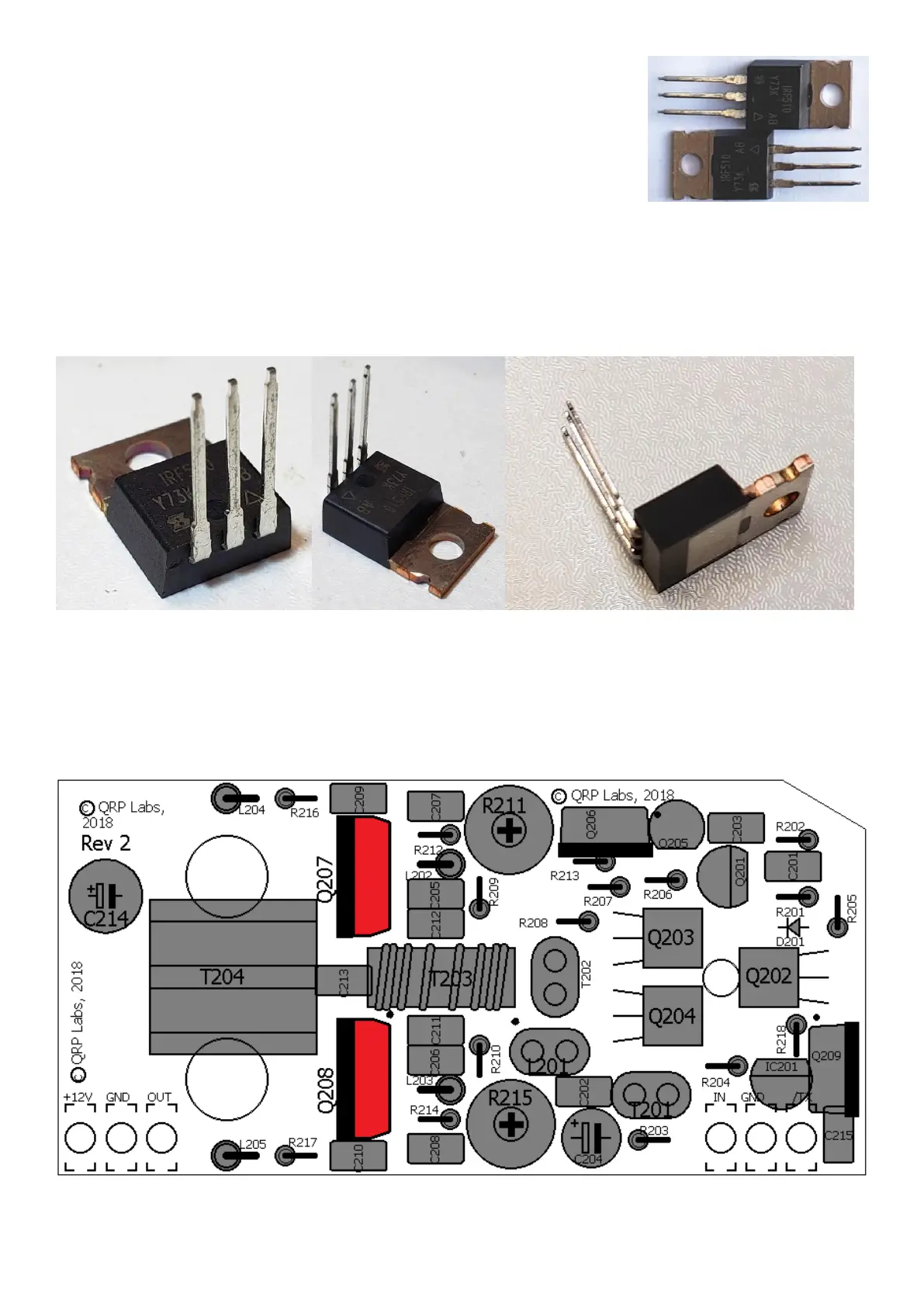
Now insert the IRF510 from below the board, and solder them on the top side (component side) of
the board. The underside of the assembled board should look like this.
Note that the M6 nut at the left is part of the assembly to the heatsink and has not been done yet
in these assembly instructions.
See next page for a photograph of the PCB bottom view. Check it before soldering Q207/8.
 Loading...