LTE Standard Module Series
EC200U_Series_Hardware_Design 43 / 94
Table 16: Pin Definition of Debug UART Interface
1.8 V power domain. If unused,
keep them open.
Table 17: Pin Definition of Auxiliary UART Interface
1.8 V power domain. If unused,
keep them open.
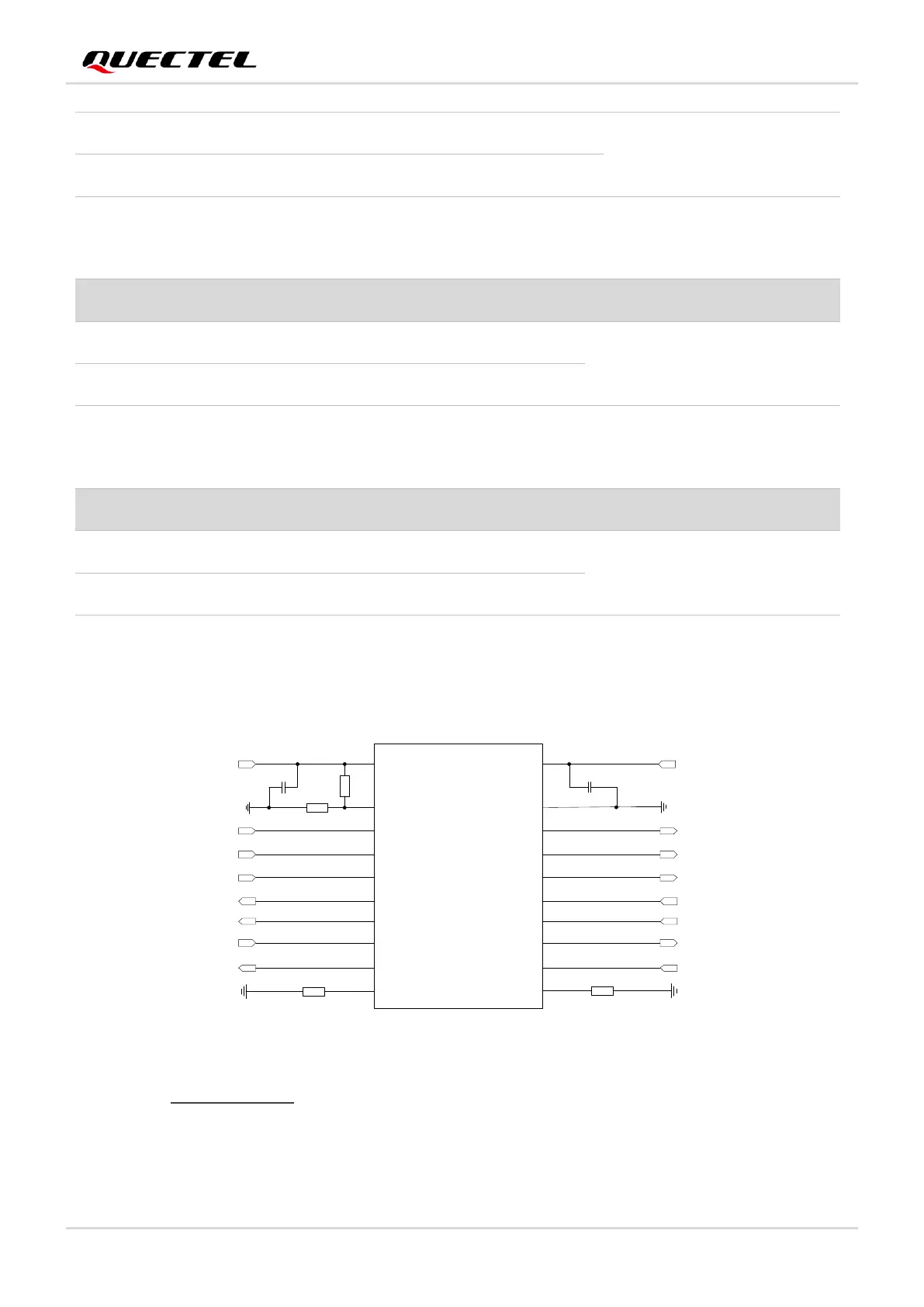
The module provides 1.8 V UART interface. Use a level shifter if the application is equipped with a 3.3 V
UART interface. A level shifter TXS0108EPWR provided by Texas Instruments is recommended. The
following figure shows a reference design.
VCCA VCCB
OE
A1
A2
A3
A4
A5
A6
A7
A8
GND
B1
B2
B3
B4
B5
B6
B7
B8
VDD_EXT
MAIN_RI
MAIN_DCD
MAIN_RTS
MAIN_RXD
MAIN_DTR
MAIN_CTS
MAIN_TXD
51K
51K
0.1 μF
0.1 μF
RI_MCU
DCD_MCU
RTS_MCU
TXD_MCU
DTR_MCU
CTS_MCU
RXD_MCU
VDD_MCU
Translator
10K
120K
Figure 20: Reference Circuit with Translator Chip
Please visit http://www.ti.com for more information.
Another example with transistor circuit is shown as below. For the design of circuits shown in dotted lines,
see that shown in solid lines, but pay attention to the direction of connection.

 Loading...


