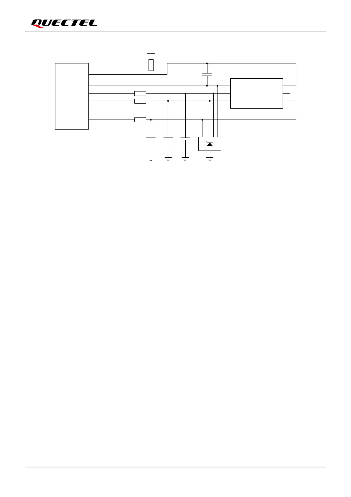
Figure 18: Reference Circuit of (U)SIM Interface with a 6-Pin (U)SIM Card Connector
In order to enhance the reliability and availability of the (U)SIM card in your applications, please follow the
criteria below in (U)SIM circuit design:
⚫ Place (U)SIM card connector as close to the module as possible. Keep the trace length less than 200
mm as far as possible.
⚫ Keep (U)SIM card signals away from RF and VBAT traces.
⚫ Keep the trace between the ground of (U)SIM card connector and USIM_GND short and wide. Keep
the trace width of USIM_GND and USIM_VDD no less than 0.5 mm to maintain the same electric
potential. If the ground is complete on your PCB, USIM_GND can be connected to PCB ground
directly.
⚫ To avoid cross-talk between USIM_DATA and USIM_CLK, keep them away from each other and
shield them with surrounded ground.
⚫ In order to offer good ESD protection, it is recommended to add a TVS diode array whose parasitic
capacitance should not be more than 15 pF. The 0 Ω resistors should be added in series between the
module and the (U)SIM card to facilitate debugging. The 33 pF capacitors on USIM_DATA,
USIM_CLK and USIM_RST are used for filtering interference of EGSM900. Please note that the
(U)SIM peripheral circuit should be close to the (U)SIM card connector.
⚫ The pull-up resistor on USIM_DATA can improve anti-jamming capability of the (U)SIM card. If the
(U)SIM card traces are too long, or the interference source is relatively close, it is recommended to
⚫ add a pull-up resistor near the (U)SIM card connector.
3.9. USB Interface
The module provides one integrated Universal Serial Bus (USB) interface which complies with the USB
2.0 specification and supports high-speed (480 Mbps) and full-speed (12 Mbps) modes. The USB

 Loading...


