M12 Hardware Design
M12_Hardware_Design_V3.3 - 43 -
Figure 23: Connection of UART3 port
3.8.4. UART Application
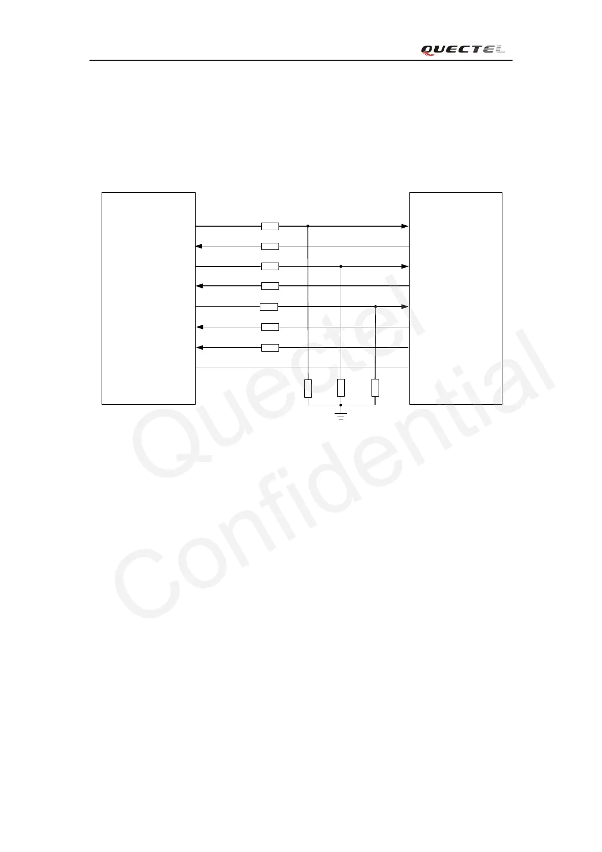
The reference design of 3.3V level match is shown as below. When the peripheral MCU/ARM
system is 3V, the divider resistor should be changed from 5.6K to 10K.
MCU/ARM
/TXD
/RXD
1K
TXD
RXD
RTS
CTS
DTR
RI
/RTS
/CTS
GPIO
EINT
GPIO DCD
Module
1K
1K
Voltage level:3.3V
5.6K
5.6K
5.6K
1K
1K
1K
1K
GND GND
Figure 24: 3.3V level match circuit
The reference design of 5V level match is shown as below. The construction of dotted line can
refer to the construction of solid line. Please pay attention to direction of connection. Input dotted
line of the module should refer to input solid line of the module. Output dotted line of module
should refer to output solid line of the module.
 Loading...


