GSM/GPRS Module Series
M35 User Manual
M35_User_Manual Confidential / Released 44 / 85
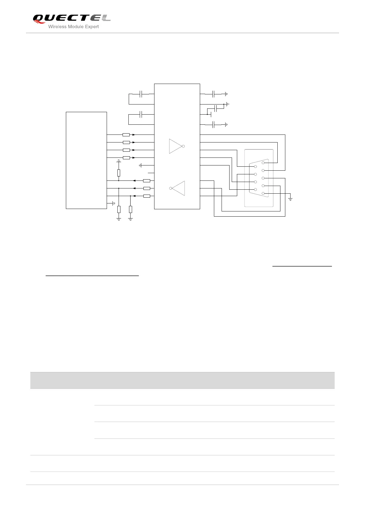
The following circuit shows a reference design for the communication between module and PC. Since the
electrical level of module is 2.8V, so a RS-232 level shifter must be used. Note that you should assure the
IO voltage of level shifter which connects to module is 2.8V.
TXD
RXD
RTS
CTS
DTR
RI
DCD
Module
GND
C1+
C1-
C2+
C2-
V+
VCC
GND
V-
3.3V
T1IN
T2IN
T3IN
T4IN
R1IN
R2IN
R3IN
R1OUT
R2OUT
R3OUT
T1OUT
T2OUT
T5OUT
T3OUT
T4OUT
T5IN
GND
GND
/R1OUT
1
2
3
4
5
6
7
8
9
GND
To PC Serial Port
GND
1K
1K
1K
1K
1K
5.6K5.6K
1K
1K
5.6K
RS-232 Level Shifter
Figure 23: Sketch Map for RS-232 Interface Match
Please visit vendor web site to select the suitable RS-232 level shifter IC, such as: http://www.exar.com/
and http://www.maximintegrated.com.
3.8. Audio Interfaces
The module provides two analogy input channels and two analogy output channels.
Table 9: Pin Definition of Audio Interface
Channel 1 Microphone positive input
Channel 1 Microphone negative input
Channel 1 Audio positive output
Channel 1 Audio negative output
Form a pseudo-differential pair with SPK2P

 Loading...


