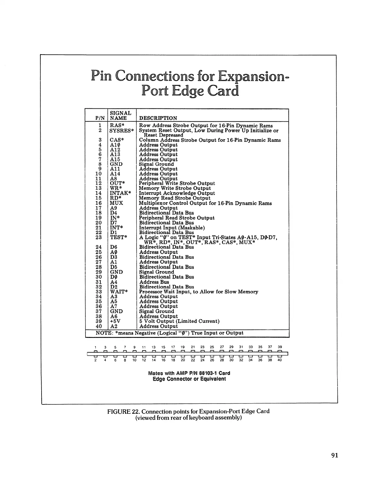
Pin Connections for Expansion-
Port
Edge
Card
SIGNAL
PIN NAME DESCRIPTION
1 RAS*
Row
Address
Strobe
Output
for
16-Pin Dynamic
Rams
2
SYSRES*
System
Reset
Output,
Low
During
Power
Up
Initialize
or
Reset
Depressed
3 CAS*
Column
Address
Strobe
Output
for
16-Pin Dynamic
Rams
4
A10
Address
Output
5
A12
Address
Output
6
A13
Address
Output
7
A15
Address
Output
8 GND
< SiEial
Ground
9
All
A dress
Output
10
A14
Address
Output
11
A8
Address
O~ut
12
OUT*
Peripheral
rite
Strobe
Output
13
WR*
Memory
Write
Strobe
Output
14
INTAK*
Interrupt
Acknowledge
Output
15
RD*
Memory
Read
Strobe
Output
16
MUX Multiplexor
Control
Output
for
16-Pin Dynamic Rams
17
A9
Address
Ou:rut
18
D4
Bidirection
Data
Bus
19
IN*
Peripheral
Read
Strobe
Output
20
D7 Bidirectional
Data
Bus
21 INT*
Interrupt
I~ut
(Maskable)
I
22
DI
Bidirection
Data
Bus
23 TEST*
A Logic
"0"
on
TEST*
Input
Tri-States
A0-A15,
D0-D7,
WR*
RD*
IN* OUT* RAS* CAS* MUX*
24 D6
Bidirectional'Data'Bus'
, ,
25
A0
Address
Output
26
D3
Bidirectional
Data
Bus
27
Al
Address
Output
I
28 D5
Bidirectional
Data
Bus
I
29
GND
Signal
Ground
i
30
D0
Bidirectional
Data
Bus
31 A4 Address Bus
32
D2
Bidirectional
Data
Bus
33
WAIT*
Processor Wait
Input,
to
Allow
for
Slow
Memory
34
A3
Address
Output
35
A5
Address
Output
36
A7
Address
Output
37
GND
Signal
Ground
38
A6
.Address
Output
39
+5V 5
Volt
Output
(Limited
Current)
40
A2
Address
Output
NOTE: *means Negative (Logical
"0")
True
Input
or
Output
1 3 5 7 9
11
13 15
17
19
21
23
25
27
29
31
33 35 37 39
: : : : : : : : ============
2 4 6 8 10 12 14 16 18 20
22
24 26 28 30 32 34 36 38 40
Mates with AMP
PIN
88103·1
Card
Edge
Connector
or
Equivalent
FIGURE 22. Connection points for Expansion-Port Edge
Card
(viewed from
rear
of keyboard assembly)
91
 Loading...