Using a Single HSS Unit
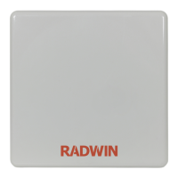
Figure 7-5: HSS Wiring schematic
The wiring, as shown in Figure 7-5 is self explanatory. The Sync signal path is less self evi-
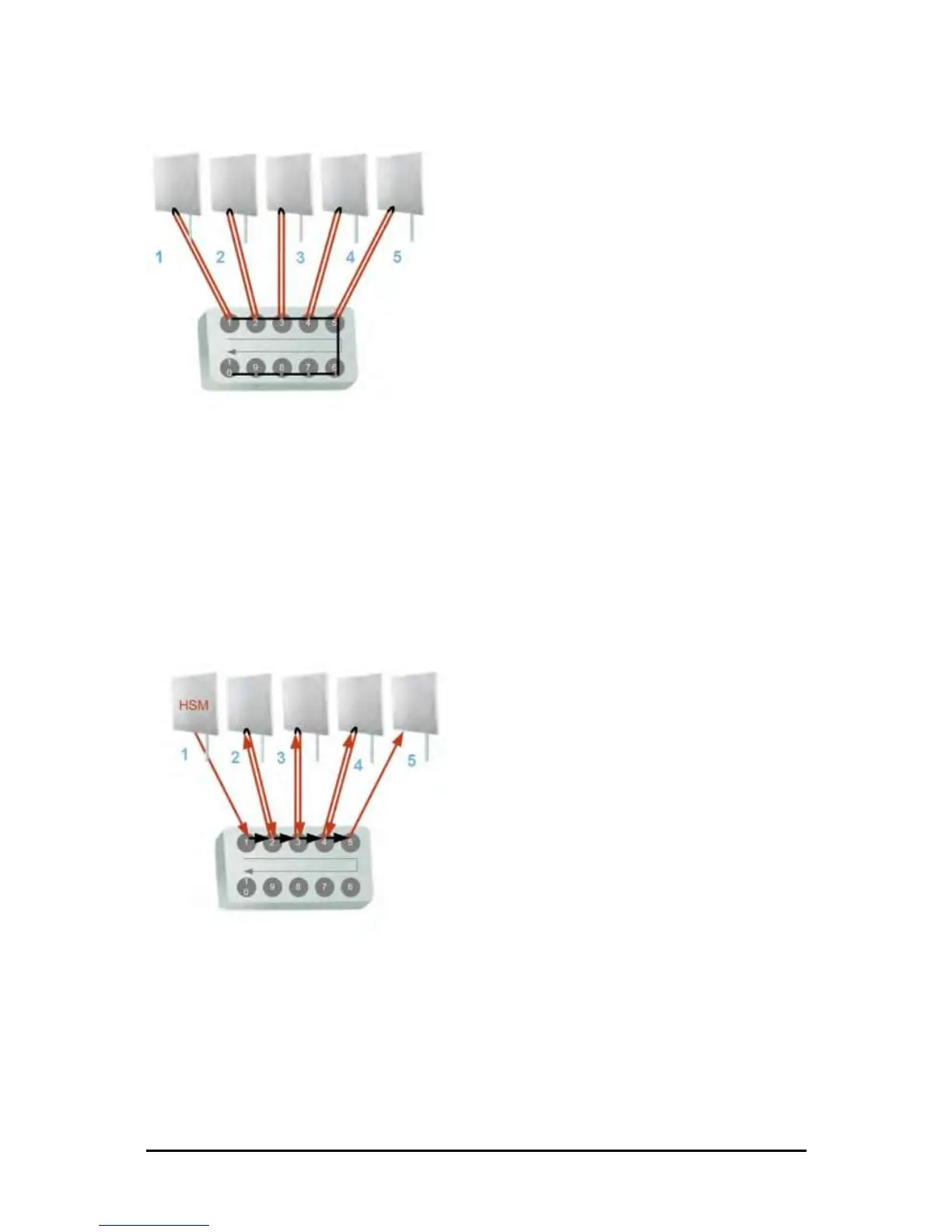
dent. If we set ODU 1 (on SYNC 1) to HSS Master, then the Sync signal path is as shown in
Figure 7-6. The signal travels from ODU 1 to SYNC 1, from SYNC 1 to SYNC 2, from SYNC 2
to ODU 2 and back again. The back and forth paths repeat for the second to fourth ODU,
from left to right. The signal exits the HSS unit at SYNC 5 and terminates in ODU 5.
The choice of the ODU on SYNC 1 as HSS master is not mandatory, but is good practice. If for
example we were to use ODU 3 as HSS master, the Sync signal path would be ODU 3 to SYNC
3, then left and right to SYNC 2 and SYNC 4. It would then propagate to ODUs 2 and 4, termi-
nating at both ODUs 1 and 5.
Figure 7-6: HSS sync signal path with ODU 1 as HSS Master
Using More than One HSS Unit
In a large collocation site, several HSS units may be cascaded (daisy-chained) subject to the
following conditions:
Condition 1: Cabling Sequence
1. Up to nine ODUs may be connected to the first HSS unit using HSS ports SYNC 1, SYNC 2,
SYNC 3,... up to SYNC 9 in order without leaving empty ports.
 Loading...