2.2 DRIVE SYSTEM
The following notes describe the installation of
both the rotary, linear and hydraulic drive units.
2.2.1 ROTARY DRIVE UNIT
The rotary drive unit is coupled to the steering
mechanism by a simple chain drive. Most steering
gear manufacturers supply special autopilot drive
attachments and many include this facility as
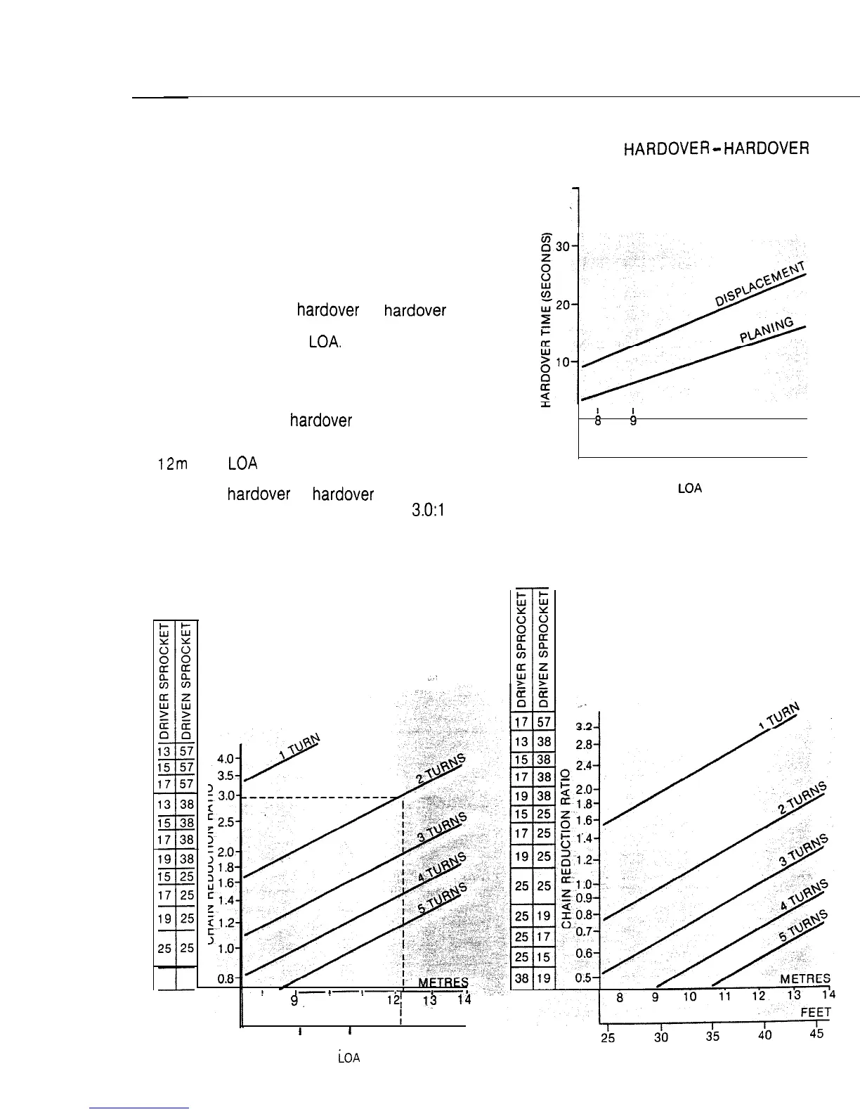
standard. Figs. 15 and 17 show the
recommended rudder
hardover
to
hardover
times for both planing and displacement
vessels up to 20m (60’)
LOA.
Figs. 16 and 18
enable the optimum chain reduction radio to be
selected for both planing and displacement
vessels. It is first necessary to determine the
number of turns of the driven sprocket when the
rudder is driven from
hardover
to hardover.
Example:
A
12m
(40’)
LOA
displacement vessel requiring
two turns of the driven sprocket to drive the
rudder from hardover to
hardover
will require a
chain reduction ratio of approximately
3.0:1
(as
indicated by the dotted line on the chart).
NPE 1: ROTARY DRIVE CHAIN
REDUCTION RATIOS
Displacement Craft
..’
TYPE 1:
HARDOVER
-
HARDOVER
TIME RECOMMENDATIONS
40
1
Fig. 15
METRES
Q
B
10 I 11 I 12 I 13 I 14 1
FEET
I
I
I
I I
25
30
35
40
45
LOA
Planing Craft
8
9,
10
11 12;
13
14
I
FEET
I
I
I I
I
25 30 35
40
45
iOA
LO A
 Loading...