2.3 CABLING AND POWER SUPPLIES
2.3.1 SIGNAL CABLING
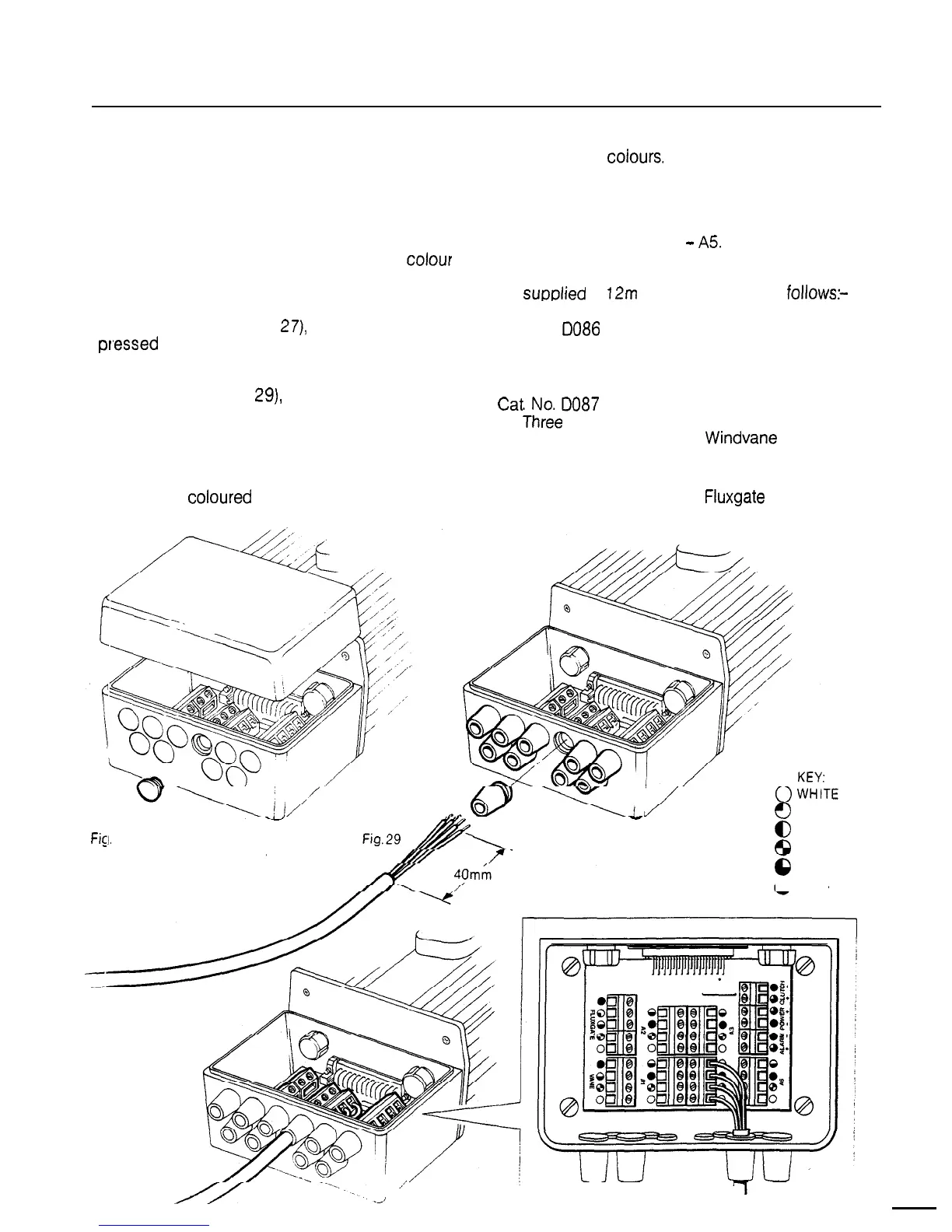
Cable interconnections between all sub system
modules are shown schematically in (Fig. 1). All
peripheral units connect to the connector unit
where they are permanently hard wired to colour
coded connector blocks situated on a central
printed circuit board (Fig. 30).
individual wire colours. The cable screen should
be connected to terminals identified by a white
dot.
The control units and the Radio Navigation
Interface may be connected to any of the serial
bus connector blocks Al
-
A5
Each peripheral unit is supplied with 6m (20’)
of interconnecting cable. Additional cabling can
be
supolied
in
12m
(40’) cut lengths as
follows:-
The end face of the connector unit is fitted with
.
ten blanking discs (Fig.
27),
which are easily
Cat. No. 0086
pr,essed
out and replaced by the special rubber
Two core unscreened
grommets supplied with each peripheral unit
fixing kit (Fig. 28). After cutting the interconnecting
cable to length (Fig.
29),
it may be passed through
the inserted rubber grommet and prepared for
Cat No
D087
connection to the relevant connector block
Three
core screened
(Fig. 30).
Alarm, Electronic
power supply and
Clutch
Control units,
Windvane
and Radio
Navigation Interface
Each connector block is clearly identified on
the printed circuit board and each wire position is
identified by coloured dots which match the
Cat. No. DO88
Four core screened
Fluxgate Compass
Fig. 27
1
f)
YELLOW
Fig. 28
@
GREEN
6
RED
0
BROWN
l
BLUE
,’
Fig. 30
I I
.-I
 Loading...