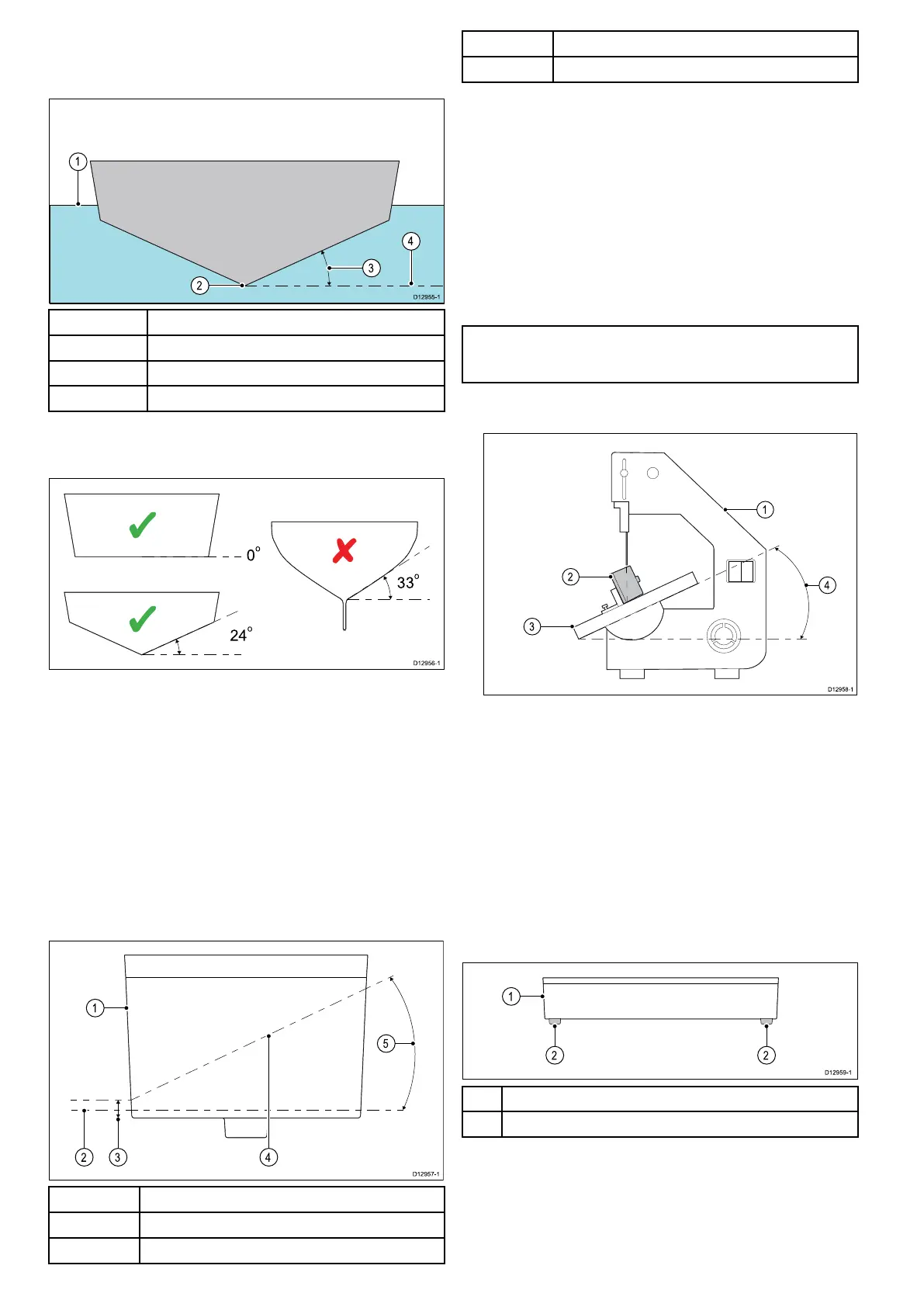
6.1 Dead rise angle
The dead rise angle is the angle of the vessels hull from the
centerline.
1 Waterline
2
Centerline
3 Dead Rise Angle
4 Parallel with waterline
The dead rise angle should be measured on the outside of the
hull using an angle nder or similar device.
Example dead rise angles
• Bronze transducer — The dead rise block is not required on
hulls with a at bottom. For hulls with a dead rise angle the
block should always be used.
• Plastic transducer — On a hull with a at bottom the Dead
rise block does not require cutting and should be used inside
the hull. For hulls with a dead rise angle the block should
always be used.
Cutting the Dead rise block
Unless the vessel hull has a at bottom, the Dead rise block
must be cut to the shape of the hull, do NOT over tighten the
nut in an attempt to close any gaps between the block and hull
as this may damage the transducer and Dead rise block. The
Dead rise block is not suitable for vessels with a dead rise angle
greater than 25 degrees.
1
Dead Rise block (Front of block facing forward)
2 Parallel to waterline
3
4 mm (0.16 in) gap minimum
4
Slope of hull
5
Dead rise angle 25 degrees maximum
1. Calculate the dead rise angle.
The dead rise angle should be measured on the outside of
the hull from the location that the transducer is to be mounted
using an angle nder or similar device.
2. Adjust the band saw table to the measured angle of your
dead rise
3. Position the dead rise block on the band saw table so that
the top of the block is against the band saw’s cutting guide.
4. Ensure that the block is correctly orientated, the arrow on top
of the Dead rise block should be pointing towards the bow
of the vessel.
5. Position the Dead rise block and cutting guide so that the cut
will create 2 equally sized parts.
Note: You must leave a minimum of 4 mm (0.16 in) gap from
the bottom of the Dead rise block as shown in the diagram
above.
6. Recheck steps 1 to 5.
7. Cut the block.
Retain the top half of the block as this will provide a level
surface inside the hull to tighten the nut against.
8. Check the bottom half of the dead rise block against the hull
to ensure a good t.
Ensure that the block runs parallel to the centerline of the
vessel.
9. If there are gaps between the block and hull then use an
appropriate le to shape the block until a precision t is
achieved.
Removing dead rise block locators
When installing the plastic transducer on a vessel with no dead
rise you must remove the locators from the bottom of the dead
rise block.
1 Dead rise block
2
locators (for locating on the transducer)
1. Remove the dead rise block from the transducer.
2. Using a suitable saw, cut the locators from the bottom of the
block.
The block is now ready to be used inside the hull as described in
the Mounting the transducer in a hull without a dead rise section.
26 CPT-70 / CPT-80 / CPT-110 / CPT-120
 Loading...