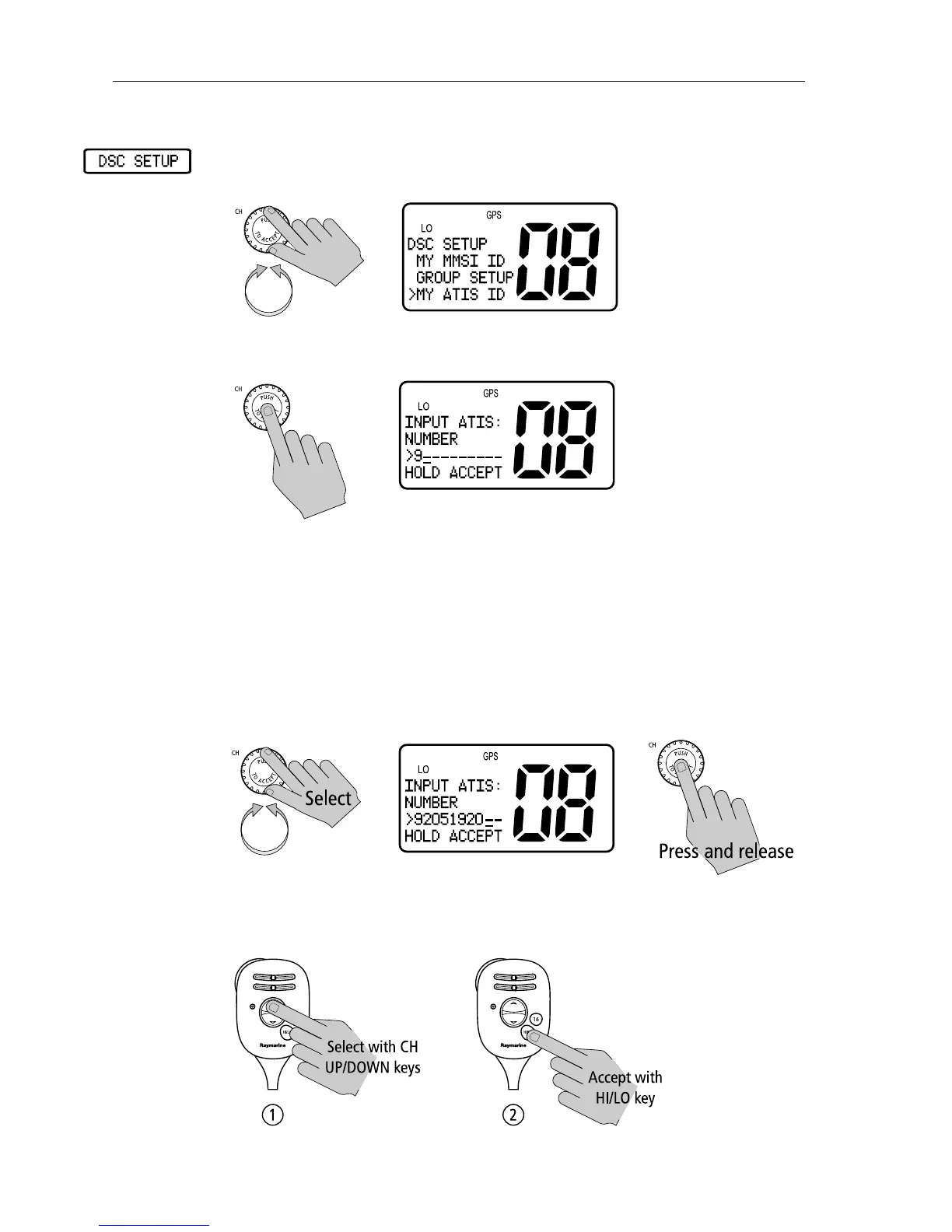
EasyManua.ls Logo

Raymarine Ray54E User Manual

Raymarine Ray54E
116 pages
To Next Page IconTo Next Page
To Previous Page IconTo Previous Page
Page #88 background imageLoading...
Page #88 background image
78 Ray54E VHF Radio
To enter or view the ATIS ID number:
1. From the DSC SETUP menu item described on page 71, rotate the CH knob
until the arrow points to MY ATIS ID.
2. Press the CH knob to accept. If an existing ATIS ID is stored, the values
appear. If the ATIS ID is blank, dashes appear, except for the initial ‘9’.
3. Rotate the CH knob or use the microphone UP/ DOWN keys to scroll
through the digits for entry into the ATIS ID field. The final available char-
acter is an arrow, which serves as a backspace. The initial character posi-
tion is indicated by a blinking underline.
When the desired character appears, press and release the CH knob or the
microphone HI/LO key to accept it. The next position now has the blink-
ing underline, indicating it is ready to be selected.
Continue in this manner until all nine digits have been selected.
You can also press the microphone UP/ DOWN keys to select each char-
acter and then press the microphone HI/LO key to accept.

Table of Contents

Other manuals for Raymarine Ray54E

Questions and Answers:

Raymarine Ray54E Specifications

General IconGeneral
TypeVHF Marine Radio
DSCYes
Display TypeLCD
Waterproof RatingIPX7
GPS InterfaceNMEA 0183
ChannelsUSA, International, and Canadian
Power Output25W (High), 1W (Low)
Weight2.6 lbs (1.2 kg)

Summary

Important Information

Maritime Mobile Service Identity (MMSI)

Explains MMSI number requirement for DSC equipment and how to obtain it.

Automatic Transmitter Identification System (ATIS)

Details ATIS functionality for inland waterways and its relation to the Basel Agreement.

SAFETY NOTICE

Antenna Mounting and EME Exposure

Guidance on optimal radio performance and minimal human exposure to RF energy.

Safe Compass Distance

Recommendations for locating the radio away from compasses for accurate readings.

Chapter 2: Installation

2.2 Planning the Installation

Guidance on selecting a suitable location for mounting the main unit.

2.3 Power Connections

Connecting the radio to the DC power source.

2.6 GPS/NMEA Data

Connecting GPS for data input.

2.7 Antenna Connections

Connecting the VHF antenna.

Chapter 3: Getting Started

3.1 Keypad and Rotary Knobs

Overview of physical controls on the radio and microphone.

Chapter 4: General Operations

4.1 Turning the Power ON and OFF

Instructions for powering the unit on and off using the PWR/VOL knob.

Chapter 5: Digital Selective Calling (DSC)

5.1 DSC Call Function

Overview of DSC Call Mode for initiating calls and accessing logs.

DISTRESS

Sending emergency calls with position and time information.

Chapter 6: Menu Settings

DSC SETUP

Configuring DSC-related functions like MMSI, ATIS, and Position Reply.

Appendix B: Channel List

Related product manuals