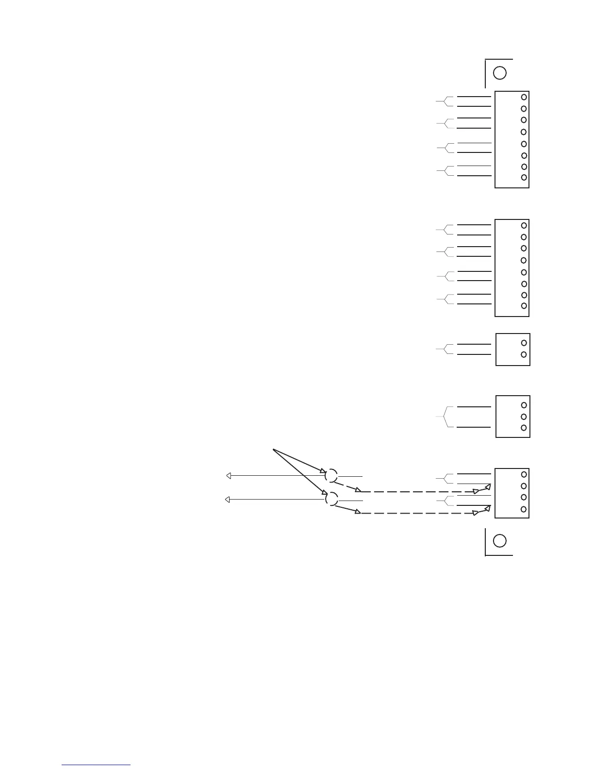
FIELD WIRING
Single-Stage (On/Off) Boilers
- All stage connections on the control
board are connected at the {TH}
(Thermostat) location on the
boiler wiring diagram.
Multiple-Stage Boilers
- First stage connections on the
control board are connected at
the {TH} (Thermostat) location
on the boiler wiring diagram.
- Second (or third, etc.) stage
connections on the control
board are connected at the
locations shown on the
boiler wiring diagram.
Utilize Shielded Cable
Outdoor Air Temperature
Sensor (see NOTE 4)
Water Temperature
Sensor
P5
Stage 1
Stage 2
Stage 3
Stage 4
1
2
3
4
5
6
7
8
Stage 5
Stage 6
Stage 7
Stage 8
Pump Relay
Pilot Duty Only
2.5 Amp Max
250V Max
Thermostat
(Jumpered) or
Building Management System
Outdoor Temp
Water Temp
1
2
3
P1
1
2
P4
P6
1
2
3
4
5
6
7
8
P2
1
2
3
4
Notes:
1. Tighten terminal strip clamping screws to 4 in-lbs. Breakage from over torquing is not covered under warranty.
2. Use copper conductors only.
3. For supply connections, use wires sized on the basis of 60°C (140°F) ampacity and rated a min. 90°C (194°F).
4. The outdoor sensor must be connected, otherwise a sensor error will be displayed.
13
 Loading...