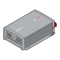
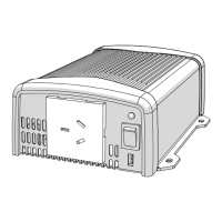
12 | Rear Panel Overview
2.1 COMMUNICATION AND REMOTE INTERFACE
The RS3 Inverters can be controlled by compatible REDARC products including the REMOTE-RS
Remote Control and the TVMS1280 via RS-232 communications using the RJ11 Interface. To enable
this, set the Main Switch to the 'REMO' position.
Pin Number Signal Description
1 Reserved --
2 GND Same as Battery Negative
3 RXD RS-232 RXD
4 TXD RS-232 TXD
5 RMT Remote Control panel (positive)
6 VCC (12 V) Internal power for Remote Control
2.2 REMOTE CONTROL TERMINAL
The Remote Control Terminal allows the installer to connect a remote
ON/OFF switch and a remote fault indicator in applications where the
inverter unit is mounted out of sight or is hard to access by the user.
Pin Number Signal Description
1 ENB− Enable −
2 ENB+ Enable +
3 N.C
Dry contact (by a relay), Normally closed
(30 VDC/2 A, surge current 7.5 A)
4 COM Dry contact (by a relay), Common
5 N.O
Dry contact (by a relay), Normally open (30 VDC/2 A,
surge current 7.5 A)
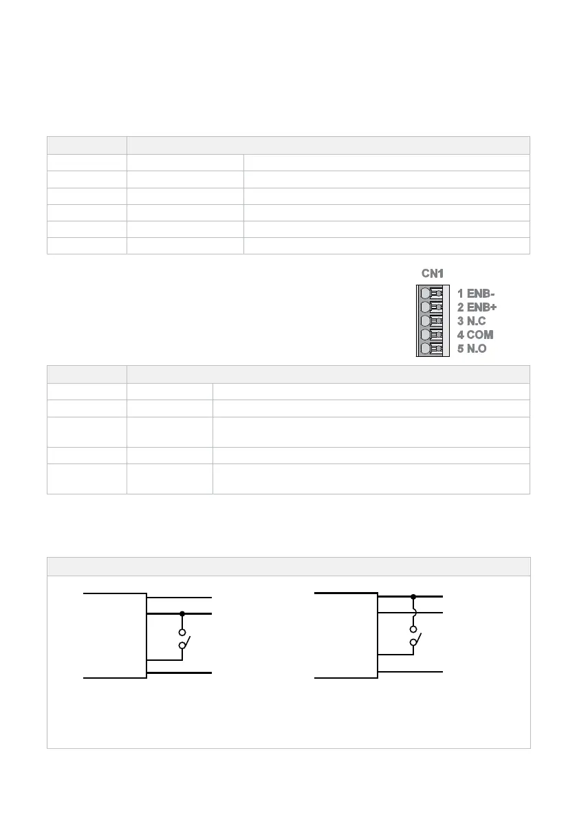
PIN 1 (ENB–) AND PIN 2 (ENB+)
Pin 1 (ENB–) and Pin 2 (ENB+) can be connected to a toggle switch to provide remote switching.
Figure 5: Wiring configurations for Inverter Remote Switch
ENB−
Chassis
Ground
Switch
BAT−
Switch ON: INV. ON
Switch OFF: INV. OFF
ENB+
Chassis
Ground
Switch
BAT−
 Loading...