Rear Panel Overview | 13
PIN 3 (N.C), PIN 4 (COM) AND PIN 5 (N.O)
Pins 3, 4 and 5 are contacts of a Form C relay circuit that can be used to connect remote status
indicators such as LED's. The relay is rated up to 30 VDC / 2 A. When the Inverter is in a "FAULT"
condition, the relay will switch Pin 4 (COM) from Pin 3 (N.C) and make contact with Pin 5 (N.O).
This relay is switched when a fault condition occurs including:
Input Over / Under Voltage
Output Short Circuit / Overload
Under / Over Temperature
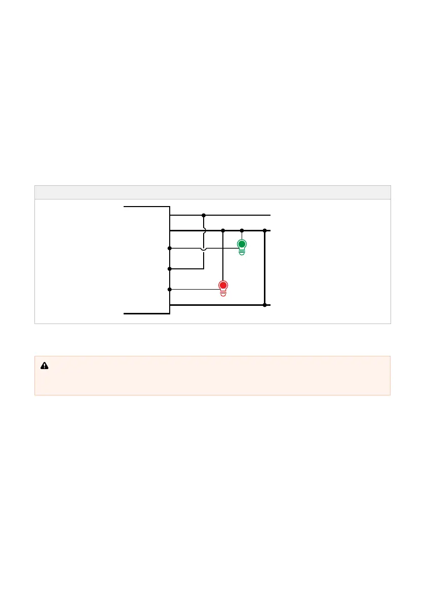
For example, the installer may want to connect LED indicators if the Inverter is operating normally or in
a fault condition. To do this, the installer may connect Pin 4 (COM) to battery positive (BAT+), a "OK"
LED to Pin 3 (N.C) and a "Fault" LED to Pin 5 (N.O).
Figure 6: Example Wiring Configuration for Inverter Remote Status Indication
Chassis
Ground
FAULT
OK
BAT+
BAT−
3. N.C
4. COM
5. N.O
2.3 CHASSIS GROUND
WARNING: Risk of electrical shock. Operation of the inverter without a proper ground connection
may result in an electrical safety hazard. Ensure proper ground connection is made during installation.
For fixed and/or transportable (vehicle) installations, install according to appropriate AS/NZS standard.
Always connect chassis ground to battery negative and use at least 2.5 mm² (14 AWG) or a thicker
cable. See page18 for guidance when installing the chassis ground connection.
 Loading...