RL78/G13 Clock Generator (Clock Switching) CC-RL
R01AN2831EJ0100 Rev. 1.00 Page 26 of 51
May 28, 2015
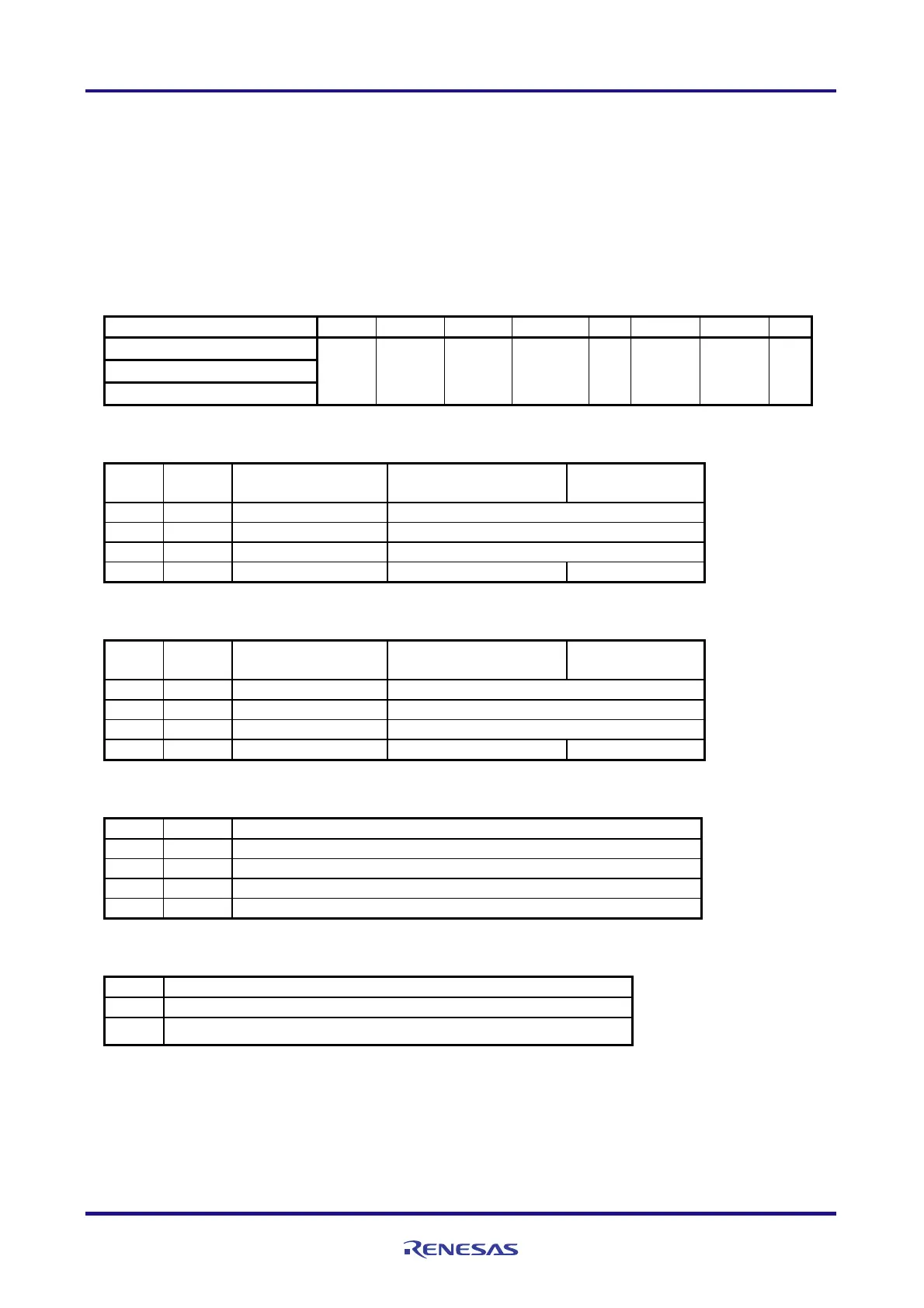
Setting up clock generator operation mode
Clock operation mode control register (CMC)
: Select high-speed system clock pin operation mode.
Select subsystem clock pin operation mode.
Select XT1 oscillator oscillation mode.
Control X1 clock frequency.
Symbol: CMC
7 6 5 4 3 2 1 0
EXCLK OSCSEL EXCLKS OSCSELS 0 AMPHS1 AMPHS0 AMPH
When HOCO clock is used 0 1 0 1 0 0 0 1
When X1 oscillation clock is used
When XT1 oscillation clock is used
Bits 7 and 6
EXCLK OSCSEL
High-speed system clock
pin operation mode
X1/P121 pin X2/EXCLK/P122 pin
0 0 Input port mode Input mode
0 1 X1 oscillation mode Crystal/ceramic resonator connection
1 0 Input port mode Input mode
1 1 External clock input mode Input mode External clock input
Bits 5 and 4
EXCLKS OSCSELS
Subsystem clock
pin operation mode
XT1/P123 pin XT2/EXCLKS/P124 pin
0 0 Input port mode Input mode
0 1 XT1 oscillation mode Crystal resonator connection
1 0 Input port mode Input mode
1 1 External clock input mode Input mode External clock input
Bits 2 and 1
AMPHS1 AMPHS0 XT1 oscillator oscillation mode selection
0 0 Low power consumption oscillation (default) Oscillation margin: Medium
0 1 Normal oscillation Oscillation margin: High
1 0 Ultra-low power consumption oscillation Oscillation margin: Low
1 1 Setting prohibited
Bit 0
AMPHS Control of X1 clock oscillation frequency
0 1 MHz fx 10 MHz
1 10 MHz < fx 20 MHz
Caution: For details on the register setup procedures, refer to RL78/G13 User's Manual: Hardware.

 Loading...


