RL78/G13 Clock Generator (Clock Switching) CC-RL
R01AN2831EJ0100 Rev. 1.00 Page 4 of 51
May 28, 2015
1. Specifications
The sample code covered in this application note switches its operating clock when the switch on the target board is
pressed according to the sequence below.
(1) High-speed on-chip oscillator clock (32 MHz) X1 oscillation clock (20 MHz)
(2) X1 oscillation clock (20 MHz) XT1 oscillation clock (32.768 kHz)
(3) XT1 oscillation clock (32.768 kHz) High-speed on-chip oscillator clock (32 MHz)
Subsequently, steps (1) to (3) are repeated.
The sample code takes the following actions according to its operating state:
When the high-speed on-chip oscillator clock (HOCO clock) operates: Stops the X1 oscillation clock.
When the X1 oscillation clock operates: Stops the HOCO clock.
When the XT1 oscillation clock operates: Stops the X1 oscillation clock and the HOCO clock.
The XT1 oscillation clock is always generated.
The sample code also changes the LED blinking period on the target board as shown below according to the operating
clock. This allows the operating clock to be visually checked.
LED blinking period of the HOCO clock (32 MHz): 0.5 seconds
LED blinking period of the X1 oscillation clock (20 MHz): 1 seconds
LED blinking period of the XT1 oscillation clock (32.768 kHz): 2 seconds
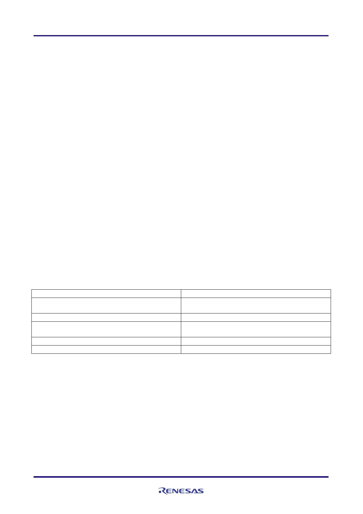
Table 1.1 summarizes the peripheral functions to be used and their uses. Figure 1.1 shows the outline of the clock
switching.
Table 1.1 Peripheral Functions to be Used and their Uses
Peripheral Function Use
Clock generator
Generates oscillation clocks and switches the operating
clocks.
External interrupt input (INTP0) Detects the press of the switch.
Timer array unit 0 channel 0
Generates the timing signal to determine the LED blinking
period.
12-bit interval timer Generates the wait time to deal with chattering.
P62 Generates the output signal to the LED.
 Loading...


